Wiring Test via the “I/O Check” View
In the I/O Check view, you can perform a wiring test for conventional analog and digital inputs/outputs of a device. Output signals can be set for test purposes (“control mode”) or input states can be read into the corresponding physical unit. If the states are visualized on the device itself, e.g., via an LED, the state is displayed in the form of an LED highlighted in a corresponding color.
- Connect your device via “Devices in the project” > [Connect].
- Open the “I/O Check” view.
- Click the eye icon
 below the device graphic.
 - Monitoring is enabled
 , i.e., current status values are displayed in tabular form.
 - The latency indicates the update cycle of the displayed device values depending on the connection, device load or other factors.
- Compare the displayed values with your hardware, e.g., whether the green LED actually lights up on your device.
- Besides value monitoring, you can also write or read them. Use the slider to switch to control mode.

- Change the individual values. For this purpose, use input fields for analog output modules and slide switches for digital output modules.
Note: Changes are not collected, writing is performed continuously during input.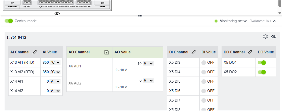
- If you want to rename channels for a better overview, click the pencil icon
 and make the change.
(Press [ESC] to exit edit mode. Changes will be discarded.) - Then click the Save icon
 or click outside the table.
 - The channel names are saved in the project file and are also displayed under “Settings” > “I/O Channels” page.
- If necessary, use the drop-down menu next to the analog values to switch between displaying raw values and scaled values with units.
When entering values, observe the specified minimum and maximum values.