Performance
The cycle time that can be reached with an EtherCAT Master depends on several significant environmental conditions, which may differ widely in different projects. Below you will find information on configuration and tips on how to recognize whether the required functionality can be provided by the device.
These factors are crucial:
- What device hardware is the software used on?
- How large is the bus's total process image?
• Depending on the devices and in some cases, their modular structure - What is the maximum cycle time that can be used to perform the control processes needed?
- Which task priority can be designated to the EtherCAT task?
- How much of the device capacity is already being utilized by other tasks?
Depending on the answers to these questions, there may be other performance restrictions to this function. The following procedure is recommended for commissioning:
Assumptions:
- A PFC200 (2nd generation) is used as the controller.
- The process image does not exceed 200 bytes (e.g., any number of 750-354 fieldbus couplers with a total of 25 8-channel digital modules).
- The process permits a maximum cycle time setting of 5 ms.
Procedure:
- Configure the modular structure of the I/O nodes and busses as described in the e!COCKPIT-manual.
- Write the PLC program, visual application, etc.
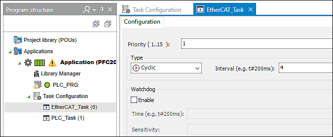
- Set the EtherCAT task cycle time to 5 ms.
- Set the EtherCAT task priority to 6.

- Download the application and start the system.
The system will now attempt to perform the required tasks. The success of this attempt can be determined with the e!COCKPIT online functions.
- Go online with e!COCKPIT
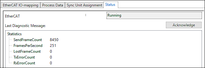
- Open the “Status” tab in the EtherCAT Fieldbus Configurator.
- In this dialog, check whether:
• The required cycle type is achieved (cycle time = 1 / FramesPerSecond [s], in this example 1 / 201 s = 47.6 ms)
• Any telegram losses or errors are displayed in the statistics

- Check whether the cycle times are maintained on average or if the jitter information changes frequently.
• Jitter (µs): Last measured jitter – Jitter is the difference between the time the task should start and the time it actually does. Example: If a task should start every 1000 µs and it only starts again after 1100 µs, the jitter is 100 µs.
• Min. jitter (µs): Minimum measured jitter
• Max. jitter (µs): Maximum measured jitter

If there are no telegram losses or errors and the jitter is not too high, the CPU load is within the required range. The system can be operated with these settings. If necessary, the cycle time can be restricted and the process checked again. However, if errors do occur during the check, try to change the settings described above to improve this state.
If there are telegram losses or errors or if the jitter is too high, even though the CPU load is within the required range (~80 %), this can be improved by setting a higher task priority (= lower number). If this does not succeed, the only remaining option is to restrict the cycle time. Or, decide whether the application can accepted even with sporadic telegram loss.
The cycle time for a PFC200 (2nd generation) should not be set to less than 2 ms.