Example Configuration for Data Exchange with a WAGO EtherNet/IP Fieldbus Coupler 750-363
The following WAGO EtherNet/IP fieldbus couplers are supported for EtherNet/IP configuration:
- 750-363
- 750-363/040-000
- 750-365/040-010
The following example uses the older version of the devices (marked as “deprecated”, see Note under WAGO Devices as EtherNet/IP Slaves) to clarify relationships, rules and definitions when setting up assemblies for input/output data points.
When the connections are configured in e!COCKPIT, the I/O data (assembly instances) to be transferred in the connection are selected. The assembly instances of a device are described in the corresponding product manual.
 Note
Note
Use the product manual of the 750-363 Fieldbus Coupler as a reference!
You need the following content from the product manual of the fieldbus coupler:
Section “I/O Modules”: This contains a list of I/O modules that can be used for applications with the fieldbus coupler.
It also lists the data that the I/O modules provide via the assembly structure for data exchange via EtherNet/IP. The corresponding data type is specified there.
Section “Assembly Object”: This describes the assembly instances for the fieldbus coupler.
Due to the modular structure of the WAGO I/O System 750, the assembly instances for input and output data points are not predefined in the EDS file. The assembly instances depend on the specific structure of the node with I/O modules. Each I/O module provides different data according to its functionality: input and output data, status and control information or diagnostic information. These can be grouped into several different types of objects using the defined static assembly classes.
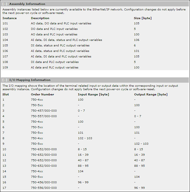
Output Assemblies
- Instance 101 (65 hex) for analog and digital output data
- Instance 102 (66 hex) for digital output data
- Instance 103 (67 hex) for analog output data
Input Assemblies
- Instance 104 (68 hex) for analog and digital input data and status*
- Instance 105 (69 hex) for digital input data and status*
- Instance 106 (6A hex) for analog input data and status*
- Instance 107 (6B hex) for digital and analog input data
- Instance 108 (6C hex) for digital input data
- Instance 109 (6D hex) for analog input data
* In the input data for instances 104, 105 and 106, an additional status byte is provided after the analog and digital input data. | |
The byte provides three status bits: | |
Bit 0: | Local bus error |
Bit 3: | I/O module diagnostics |
Bit 7: | Fieldbus error |
In the “Coupler/Controller Configuration Object (64hex)” of the fieldbus coupler, this byte corresponds to the “ProcessState” attribute (instance 1, attribute ID 5). The data type is USINT. | |
For WAGO fieldbus couplers, these instances can be configured in the path of the connection. The input/output data points for the connection must then be created according to the configuration. Manual creation only applies to the “deprecated” version of the WAGO fieldbus coupler used here. How the input/output data points are configured for the various instances is described below on the basis of an example.
Rules for Defining the Data Structure of the Assemblies
The following rules must be observed. They are based on the data structure of the WAGO I/O System 750/753s.
- The assignment is made in blocks of digital and analog input and output data.
- The internal representation of data larger than one byte uses Intel format (little-endian).
- In the structure of the modules, the complex I/O modules (analog I/O modules and I/O modules with special functions) are first incorporated according to their physical order (position) after the fieldbus coupler. They are followed by the digital I/O modules.
- Digital I/O modules provide one bit per channel for the process value. In addition, diagnostic bits can be defined for each channel.
- The data of digital I/O modules is always summarized in bytes. It is then filled in with data byte by byte according to the physical sequence.
- As soon as a whole byte is occupied by the bit-oriented digital I/O modules, the next byte is started automatically.
- I/O modules with special functions appear like analog I/O modules.
Example Nodes
The following example node shows how the data structures of the available assemblies are built up and how you can configure the data for “Input/Output” of a connection accordingly in the EtherNet/IP data point configurator in e!COCKPIT. The entries in the “Name” and “Comment” columns are examples and can be adjusted according to the application.
No. | 750-363 EtherNet/IP Fieldbus Coupler | |
1 | ├── | 750-402 (4 DIs) |
2 | ├── | 750-504 (4 DOs) |
3 | ├── | 750-457 (4 AIs +- 10 VDC SE) |
4 | ├── | 750-557 (4 AOs +- 10 VDC SE) |
5 | ├── | 753-430 (8 DIs) |
6 | ├── | 753-530 (8 DOs) |
7 | ├── | 750-1506 (8 DIs/DOs) |
8 | ├── | 750-1405 (16 DIs) |
9 | ├── | 750-1504 (16 DOs) |
10 | ├── | 750-652 (complex: RS232/485 interface) / 8 bytes |
11 | ├── | 750-652 (complex: RS232/485 interface) / 24 bytes |
12 | ├── | 750-652 (complex: RS232/485 interface) / 48 bytes |
13 | ├── | 750-652 (complex: RS232/485 interface) / 8 bytes |
14 | ├── | 750-401 (2 DIs) |
15 | ├── | 750-501 (2 DOs) |
16 | ├── | 750-456 (2 AIs +-10 VDC diff) |
17 | ├── | 750-556 (2 AOs +-10 VDC diff) |
| ├── | 750-600 End Module |
Input Data
Instance 104 (68hex) for Analog and Digital Input Data and Status
Input size (T → O): 106 bytes
Direction | Name | Data Type | Bit Size | Comments |
|---|---|---|---|---|
| Measured value AI – channel 1 | Word | 16 | 750-457 – 4 AIs – no. 3 |
| Measured value AI – channel 2 | Word | 16 | 750-457 – 4 AIs – no. 3 |
| Measured value AI – channel 3 | Word | 16 | 750-457 – 4 AIs – no. 3 |
| Measured value AI – channel 4 | Word | 16 | 750-457 – 4 AIs – no. 3 |
| Status byte S0, S1 | Word | 16 | 750-652 – 8 bytes – no. 10 |
| Data byte D0, D1 | Word | 16 | 750-652 – 8 bytes – no. 10 |
| Data byte D2, D3 | Word | 16 | 750-652 – 8 bytes – no. 10 |
| Data byte D4, D5 | Word | 16 | 750-652 – 8 bytes – no. 10 |
| Status byte S0, S1 | Word | 16 | 750-652 – 24 bytes – no. 11 |
| Data byte D0, D1 | Word | 16 | 750-652 – 24 bytes – no. 11 |
| Data byte D2, D3 | Word | 16 | 750-652 – 24 bytes – no. 11 |
| ... | |||
| Data byte D6, D7 | Word | 16 | 750-652 – 24 bytes – no. 11 |
| ... | |||
| Data byte D20, D21 | Word | 16 | 750-652 – 24 bytes – no. 11 |
| Status byte S0, S1 | Word | 16 | 750-652 – 48 bytes – no. 12 |
| Data byte D0, D1 | Word | 16 | 750-652 – 48 bytes – no. 12 |
| Data byte D2, D3 | Word | 16 | 750-652 – 48 bytes – no. 12 |
| ... | |||
| Data byte D6, D7 | Word | 16 | 750-652 – 48 bytes – no. 12 |
| ... | |||
| Data byte D22, D23 | Word | 16 | 750-652 – 48 bytes – no. 12 |
| ... | |||
| Data byte D44, D45 | Word | 16 | 750-652 – 48 bytes – no. 12 |
| Status byte S0, S1 | Word | 16 | 750-652 – 8 bytes – no. 13 |
| Data byte D0, D1 | Word | 16 | 750-652 – 8 bytes – no. 13 |
| Data byte D2, D3 | Word | 16 | 750-652 – 8 bytes – no. 13 |
| Data byte D4, D5 | Word | 16 | 750-652 – 8 bytes – no. 13 |
| Measured value AI – channel 1 | Word | 16 | 750-456 – 2 AIs – no. 16 |
| Measured value AI – channel 2 | Word | 16 | 750-456 – 2 AIs – no. 16 |
| DI data bits | Byte | 8 | 750-402 – 4 DI[1..4] – no.1, |
| DI data bits | Byte | 8 | 750-430 – 8 DI[5..8] – no.5, |
| DI data bits | Byte | 8 | 750-1506 – 8 DI[5..8] – no.7, |
| DI data bits | Byte | 8 | 750-1405 – 16 DI[5..12] – no.8 |
| DI data bits | Byte | 8 | 750-1405 – 16 DI[13..16] – no.8, |
| ProcessData | USINT | 8 | 750-363 Fieldbus Coupler |

Instance 105 (69hex) for Digital Input Data and Status
Input size (T → O): 6 bytes
The structure of the assembly is the same as for instance 104, but the data for the following I/O modules is missing: 750-457 / 750-652 – 8 bytes / 750-652 – 24 bytes / 750-652 – 48 bytes / 750-652 – 8 bytes / 750-456
Direction | Name | Data Type | Bit Size | Comments |
|---|---|---|---|---|
| DI data bits | Byte | 8 | 750-402 – 4 DI[1..4] – no.1, 750-430 – 8 DI[1..4] – no.5 |
| DI data bits | Byte | 8 | 750-430 – 8 DI[5..8] – no.5, 750-1506 – 8 DI[1..4] – no.7 |
| DI data bits | Byte | 8 | 750-1506 – 8 DI[5..8] – no.7, 750-1405 – 16 DI[1..4] – no.8 |
| DI data bits | Byte | 8 | 750-1405 – 16 DI[5..12] – no.8 |
| DI data bits | Byte | 8 | 750-1405 – 16 DI[13..16] – no.8 750-401 – 2 DI[1..2] – no.14 |
| ProcessState | USINT | 8 | 750-363 Fieldbus Coupler |
Instance 106 (6Ahex) for Analog Input Data and Status
Input size (T → O): 101 bytes
The structure of the assembly is the same as for instance 104, but the data for the following I/O modules is missing: 750-402 / 750-430 / 750-1506 / 750-1405 / 750-401
Direction | Name | Data Type | Bit Size | Comments |
|---|---|---|---|---|
| Measured value AI – channel 1 | Word | 16 | 750-457 – 4 AIs – no. 3 |
| Measured value AI – channel 2 | Word | 16 | 750-457 – 4 AIs – no. 3 |
| Measured value AI – channel 3 | Word | 16 | 750-457 – 4 AIs – no. 3 |
| Measured value AI – channel 4 | Word | 16 | 750-457 – 4 AIs – no. 3 |
| Status byte S0, S1 | Word | 16 | 750-652 – 8 bytes – no. 10 |
| Data byte D0, D1 | Word | 16 | 750-652 – 8 bytes – no. 10 |
| Data byte D2, D3 | Word | 16 | 750-652 – 8 bytes – no. 10 |
| Data byte D4, D5 | Word | 16 | 750-652 – 8 bytes – no. 10 |
| Status byte S0, S1 | Word | 16 | 750-652 – 24 bytes – no. 11 |
| Data byte D0, D1 | Word | 16 | 750-652 – 24 bytes – no. 11 |
| Data byte D2, D3 | Word | 16 | 750-652 – 24 bytes – no. 11 |
| ... | |||
| Data byte D6, D7 | Word | 16 | 750-652 – 24 bytes – no. 11 |
| ... |
| ||
| Data byte D20, D21 | Word | 16 | 750-652 – 24 bytes – no. 11 |
| Status byte S0, S1 | Word | 16 | 750-652 – 48 bytes – no. 12 |
| Data byte D0, D1 | Word | 16 | 750-652 – 48 bytes – no. 12 |
| Data byte D2, D3 | Word | 16 | 750-652 – 48 bytes – no. 12 |
| ... | |||
| Data byte D6, D7 | Word | 16 | 750-652 – 48 bytes – no. 12 |
| ... | |||
| Data byte D22, D23 | Word | 16 | 750-652 – 48 bytes – no. 12 |
| Data byte D44, D45 | Word | 16 | 750-652 – 48 bytes – no. 12 |
| Status byte S0, S1 | Word | 16 | 750-652 – 8 bytes – no. 13 |
| Data byte D0, D1 | Word | 16 | 750-652 – 8 bytes – no. 13 |
| Data byte D2, D3 | Word | 16 | 750-652 – 8 bytes – no. 13 |
| Data byte D4, D5 | Word | 16 | 750-652 – 8 bytes – no. 13 |
| Measured value AI – channel 1 | Word | 16 | 750-456 – 2 AIs – no. 16 |
| Measured value AI – channel 2 | Word | 16 | 750-456 – 2 AIs – no. 16 |
| ProcessState | USINT | 8 | 750-363 Fieldbus Coupler |
Instance 107 (6Bhex) for Digital and Analog Input Data
Input size (T → O): 105 bytes
The structure of the assembly is the same as for instance 104, but the ProcessState is missing.
Instance 108 (6Chex) for Digital Input Data
Input size (T → O): 5 bytes
The structure of the assembly is the same as for instance 105, but the ProcessState is missing.
Instance 109 (6Dhex) for Analog Input Data
Input size (T → O): 100 bytes
The structure of the assembly is the same as for instance 106, but the ProcessState is missing.
Output Data
Instance 101 (65hex) for Analog and Digital Output Data
Output size (O → T): 105 bytes
Direction | Name | Data Type | Bit Size | Comments |
|---|---|---|---|---|
| Output value AO – channel 1 | Word | 16 | 750-557 – 4 AOs – no. 4 |
| Output value AO – channel 2 | Word | 16 | 750-557 – 4 AOs – no. 4 |
| Output value AO – channel 3 | Word | 16 | 750-557 – 4 AOs – no. 4 |
| Output value AO – channel 4 | Word | 16 | 750-557 – 4 AOs – no. 4 |
| Control byte C0, C1 | Word | 16 | 750-652 – 8 bytes – no. 10 |
| Data byte D0, D1 | Word | 16 | 750-652 – 8 bytes – no. 10 |
| Data byte D2, D3 | Word | 16 | 750-652 – 8 bytes – no. 10 |
| Data byte D4, D5 | Word | 16 | 750-652 – 8 bytes – no. 10 |
| Control byte C0, C1 | Word | 16 | 750-652 – 24 bytes – no. 11 |
| Data byte D0, D1 | Word | 16 | 750-652 – 24 bytes – no. 11 |
| Data byte D2, D3 | Word | 16 | 750-652 – 24 bytes – no. 11 |
| ... | |||
| Data byte D6, D7 | Word | 16 | 750-652 – 24 bytes – no. 11 |
| ... | |||
| Data byte D20, D21 | Word | 16 | 750-652 – 24 bytes – no. 11 |
| Control byte C0, C1 | Word | 16 | 750-652 – 48 bytes – no. 12 |
| Data byte D0, D1 | Word | 16 | 750-652 – 48 bytes – no. 12 |
| Data byte D2, D3 | Word | 16 | 750-652 – 48 bytes – no. 12 |
| ... | |||
| Data byte D6, D7 | Word | 16 | 750-652 – 48 bytes – no. 12 |
| ... | |||
| Data byte D22, D23 | Word | 16 | 750-652 – 48 bytes – no. 12 |
| ... | |||
| Data byte D44, D45 | Word | 16 | 750-652 – 48 bytes – no. 12 |
| Control byte C0, C1 | Word | 16 | 750-652 – 8 bytes – no. 13 |
| Data byte D0, D1 | Word | 16 | 750-652 – 8 bytes – no. 13 |
| Data byte D2, D3 | Word | 16 | 750-652 – 8 bytes – no. 13 |
| Data byte D4, D5 | Word | 16 | 750-652 – 8 bytes – no. 13 |
| Output value AO – channel 1 | Word | 16 | 750-556 – 2 AIs – no. 17 |
| Output value AO – channel 2 | Word | 16 | 750-556 – 2 AIs – no. 17 |
| DO data bits | Byte | 8 | 750-504 – 4 DO[1..4] – no.2, 750-530 – 8 DO[1..4] – no.6 |
| DO data bits | Byte | 8 | 750-530 – 8 DO[5..8] – no.6, 750-1506 – 8 DO[1..4] – no.7 |
| DO data bits | Byte | 8 | 750-1506 – 8 DO[5..8] – no.7, 750-1504 – 16 DO[1..4] – no.9 |
| DO data bits | Byte | 8 | 750-1504 – 16 DO[5..12] – no.9 |
| DO data bits | Byte | 8 | 750-1504 – 16 DO[5..12] – no.9 |

Instance 102 (66hex) for Digital Output Data
Output size (O → T): 5 bytes
The structure of the assembly is the same as for instance 101, but the data for the following I/O modules is missing: 750-557 / 750-652 – 8 bytes / 750-652 – 24 bytes / 750-652 – 48 bytes / 750-652 – 8 bytes / 750-556
Direction | Name | Data Type | Bit Size | Comments |
|---|---|---|---|---|
| DO data bits | Byte | 8 | 750-504 – 4 DO[1..4] – no.2, 750-530 – 8 DO[1..4] – no.6 |
| DO data bits | Byte | 8 | 750-530 – 8 DO[5..8] – no.6, 750-1506 – 8 DO[1..4] – no.7 |
| DO data bits | Byte | 8 | 750-1506 – 8 DO[5..8] – no.7, 750-1504 – 16 DO[1..4] – no.9 |
| DO data bits | Byte | 8 | 750-1504 – 16 DO[5..12] – no.9 |
| DO data bits | Byte | 8 | 750-1504 – 16 DO[13..16] – no.9 750-501 – 2 DO[1..2] – no.15 |
Instance 103 (67hex) for Analog Output Data
Output size (O → T): 100 bytes
The structure of the assembly is the same as for instance 101, but the data for the following I/O modules is missing: 750-504 / 750-530 / 750-1506 / 750-1504 / 750-501.
Direction | Name | Data Type | Bit Size | Comments |
|---|---|---|---|---|
| Output value AO – channel 1 | Word | 16 | 750-557 – 4 AOs – no. 4 |
| Output value AO – channel 2 | Word | 16 | 750-557 – 4 AOs – no. 4 |
| Output value AO – channel 3 | Word | 16 | 750-557 – 4 AOs – no. 4 |
| Output value AO – channel 4 | Word | 16 | 750-557 – 4 AOs – no. 4 |
| Control byte C0, C1 | Word | 16 | 750-652 – 8 bytes – no. 10 |
| Data byte D0, D1 | Word | 16 | 750-652 – 8 bytes – no. 10 |
| Data byte D2, D3 | Word | 16 | 750-652 – 8 bytes – no. 10 |
| Data byte D4, D5 | Word | 16 | 750-652 – 8 bytes – no. 10 |
| Control byte C0, C1 | Word | 16 | 750-652 – 24 bytes – no. 11 |
| Data byte D0, D1 | Word | 16 | 750-652 – 24 bytes – no. 11 |
| Data byte D2, D3 | Word | 16 | 750-652 – 24 bytes – no. 11 |
| ... | |||
| Data byte D6, D7 | Word | 16 | 750-652 – 24 bytes – no. 11 |
| ... | Word | 16 | |
| Data byte D20, D21 | Word | 16 | 750-652 – 24 bytes – no. 11 |
| Control byte C0, C1 | Word | 16 | 750-652 – 48 bytes – no. 12 |
| Data byte D0, D1 | Word | 16 | 750-652 – 48 bytes – no. 12 |
| Data byte D2, D3 | Word | 16 | 750-652 – 48 bytes – no. 12 |
| ... | |||
| Data byte D6, D7 | Word | 16 | 750-652 – 48 bytes – no. 12 |
| ... | |||
| Data byte D22, D23 | Word | 16 | 750-652 – 48 bytes – no. 12 |
| ... | |||
| Data byte D44, D45 | Word | 16 | 750-652 – 48 bytes – no. 12 |
| Control byte C0, C1 | Word | 16 | 750-652 – 8 bytes – no. 13 |
| Data byte D0, D1 | Word | 16 | 750-652 – 8 bytes – no. 13 |
| Data byte D2, D3 | Word | 16 | 750-652 – 8 bytes – no. 13 |
| Data byte D4, D5 | Word | 16 | 750-652 – 8 bytes – no. 13 |
| Output value AO – channel 1 | Word | 16 | 750-556 – 2 AIs – no. 17 |
| Output value AO – channel 2 | Word | 16 | 750-556 – 2 AIs – no. 17 |
Testing the Configuration in Web-Based Management
The “I/O Data” page of the Web-Based Management of the fieldbus coupler shows all the input and output channels with the values that were specified or read out within the program.
On the “EtherNet/IP” page you can also see the assembly sizes used. Here “Slot” indicates the position number of the I/O module.