Connecting Controller (Master) to Controller (CODESYS V2) (Slave)
The basic procedure largely corresponds to the description in Connecting Controller (Master) to Fieldbus Coupler (Slave). The main difference is that controllers that are programmed with CODESYS V2, not with e!COCKPIT, are used as slaves. You can integrate existing controllers with CODESYS V2 projects into a Modbus network in e!COCKPIT and access its I/O modules, but not the variables of the controller program.
Place Devices on the Communication View
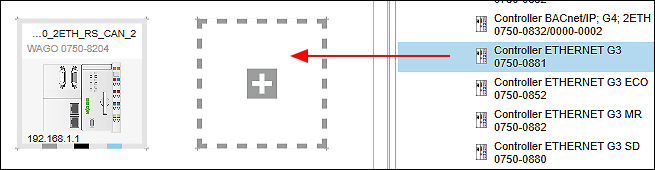
- Select the controllers from the product catalog and use the mouse to drag them into the Network view (communication view).
Configure I/O Modules Used in the Device Detail View
- Open the Device Detail view (in either graphical and tabular view) by double-clicking the controller.
- Arrange the I/O modules used analogously to your hardware by dragging them from the product catalog and positioning them after the device.
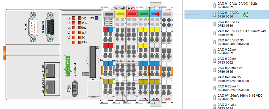
- Parameterize the I/O modules as needed by selecting them and making changes on the “Settings” panel for each.
- Go back to the Network view.
- Proceed in the same way with the second device.
Connect Devices
- Click the gray connector (ETHERNET/Modbus) for one of the devices in the Network view (communication view) and hold down the mouse button.
- To connect the devices to each other, drag the connection line to the same type connector on the second device. Release the mouse button as soon as a green plus sign appears.
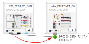
- The devices are connected. The arrow of the connection line indicates the automatically assigned roles of the device: The connection line starts at the master and ends at the slave.
Set the Protocol for the Connection
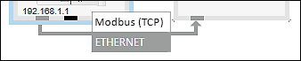
- To set the protocol for the connection, click the [Protocol] button in the context menu of the Modbus connector or connection.
- Select the desired connection (in this example: “Modbus (TCP)”).
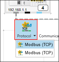
The selection options depend on the devices used.
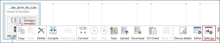
Make the Device Settings on the “Settings” Panel
You can change the settings or parameters of the devices that have been added on the “Settings” panel. The panel is open by default. If it is not, open it using the context menu of the device and the [Settings] button.
- Select the device in the network view.
- The tabs, entry screens and selection fields on the “Settings” panel depend on the specific device. The settings options displayed depend on the content of the particular device description file.
- Make all the general settings concerning the device, PLC and local bus on the first tabs. For example, you can change the IP address.
- Make Modbus settings on the “Modbus” tab.
- Proceed in the same way with the second device.
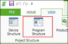
Program Application
Below you will create an application for the controller (here: PFC200, 750-8204). Note that the CODESYS V2-compatible controller (here: 750-881) cannot be programmed with e!COCKPIT (CODESYS V3).
- Select the controller (master).
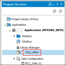
- Open the “Program Structure” panel by clicking the [Program Structure] button on the “VIEW” tab of the menu ribbon.
- Create your program (in the main “PLC_PRG” program or in a POU).
- Compile and validate your program on the “PROGRAM” tab with [Compile].
Configure Slave
You configure the slave in the data point configurator.
- To switch to the data point configurator, double-click the Device tile of the slave device.
- The Device Detail view appears. The Modbus data point configurator opens on the “Modbus Slave” tab of the Device Detail view.
- For the controller (CODESYS V2) that is used as a slave in this case, the data point configurator serves primarily to rename data points and display existing data points.
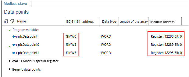
Performing “Add from Program” directly is not available under “Program variables,” since direct access to the application variables of the older CODESYS V2 is not possible. However, you can manually create and used PFC variables and variables from the flag area of the controller (CODESYS V2): - Right-click “Program variables” and [Add].
- Under “IEC 61131 Address,” modify the address of the variables from the CODESYS V2 application.
- The address describes direct memory access to the memory location indicated. You can find help on address formats in CODESYS in the CODESYS online help, “Memory Area” index.
- The Modbus address is calculated automatically and displayed.
- Optional: If necessary, you can also add generic data points in the data point configurator. You need these if you want to access existing data points, which can represent any position in the existing Modbus process image, in a certain way (using function codes), for example. For creating and editing generic data points, see scenario Connecting Controller (Master) to Controller (Slave), “Create Generic Data Points.”
Configure Connection between Master and Slaves
You can configure the connection between the master and slaves in the fieldbus configurator. Here you primarily make connection settings, display variables to transfer and create new variables.
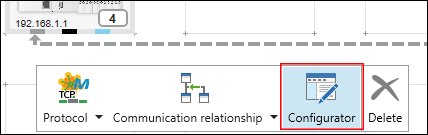
- Click the Modbus connector of one of the two connected devices.
- Open the Modbus fieldbus configurator by clicking the [Configurator] button.
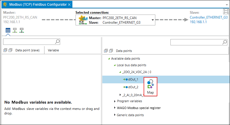
- The fieldbus configurator opens. The connection is shown in the header section of the configurator. If multiple slaves are connected to one master, you can modify the selection under “Selected Connection.”
- The fieldbus configurator is divided into two columns:
The left side shows the variables that are transferred from the slave to the master via the bus.
The right side shows the data points available on the slave. Besides “Program variables,” “Generic Data Points” and other standard variables that are automatically available to every Modbus slave (“WAGO Modbus special register”) are also shown here. - In the right-hand column, select a slave data for the master to access.
Tip: You can select multiple data points by holding down the Control key. - Click [Map] in the context menu of the data point.
- The variable is generated in the master application. This establishes the connection to the slave data point.
- You see the slave data point (1), the variable that has been created on the master (2), the drop-down list for modifying the data type (3), the cycle time for updating variables via Modbus and (4) the type of Modbus access to the variables (5).
ReadOnly (RO): Master reads the slave’s output
WriteOnly (WO): Master writes to the slave’s output
ReadWrite (RW): Master reads the output/writes to the input of the slave 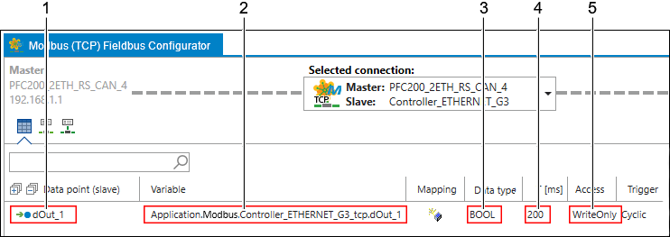
- Change the cycle time (column T [ms]) to the required cycle time.
- You can now use the master variable in the master’s application.
Access Data Points
- Open the program structure and the main program of the master.
- In the master’s application, the variable is accessed as shown in the following figure.
- Tip: Press the [F2] key to open the input assistant for easy variable selection.
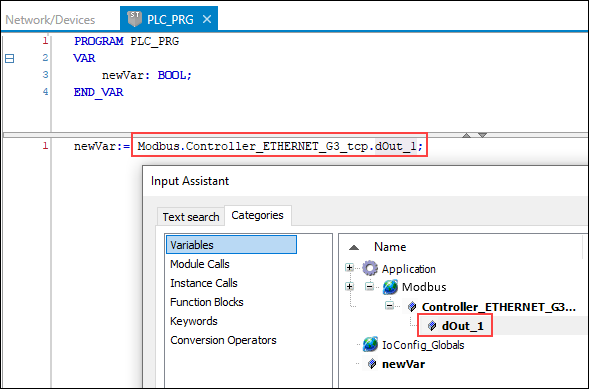
- In this way, an existing slave data point has been made accessible via Modbus and read out in the master application.