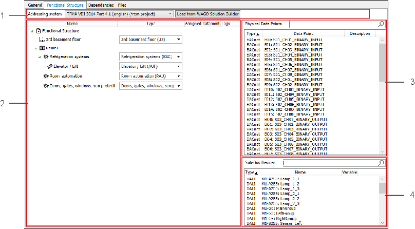
“Functional Structure“ Tab
You can use the “Functional Structure“ tab to optionally populate the Application template with a data model based on an addressing system. The data model describes data points of the application template and their functional relationships in a hierarchical structure, e.g., BACnet objects or hardware I/O.
Position | Designation | Description | |
|---|---|---|---|
1 | Addressing system | Here you can display and select the addressing system. Note: | |
[Loading | Loads the addressing systems from Solution Builder and provides them in the drop-down menu. | ||
2 | Functional Structure | Here you can configure the functional structure. Based on the selected addressing system, you can then set up a structure tree, starting from any level that ends with items of type “Data Point.” Right-clicking on an existing structural element opens a context menu; see 8 “Functional Structure” Contextual Menu below. Note: | |
Example: Assuming an Application template can control up to eight rooms, then eight individual trees are created here, beginning at the “Room“ level, and these trees assign the data points to the corresponding rooms. To link BACnet objects or hardware I/Os to data points, drag a data point from the “Physical Data Points” area and drop it on a data point in the “Functional Structure” area. | |||
3 | Physical Data Points | Displays a list of BACnet objects and hardware I/O that have not yet been assigned to a data point. Note: | |
4 | Sub-Bus Devices | Displays a list of all sub-bus devices implemented in the Application template being used. Note: | |