Device Detail View
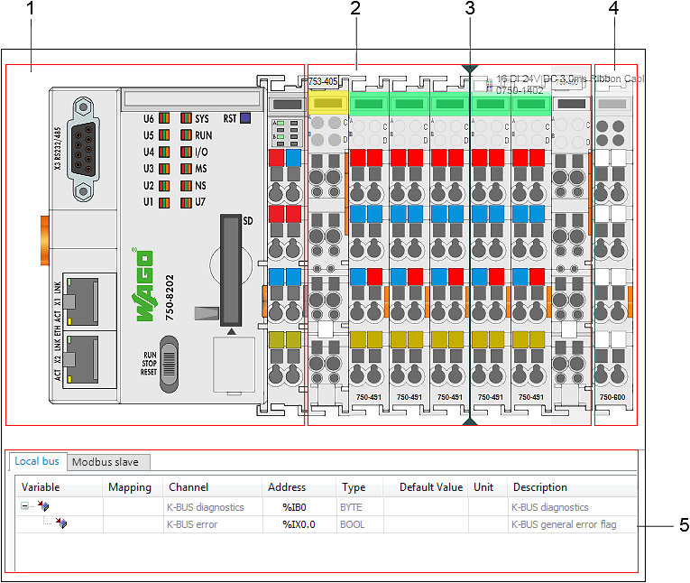
The Device Detail view is opened by double-clicking a device in the Network view. The Device Detail view is designed for each specific product series. It adds modules to a head station (via Drag & Drop from the Product Catalog), for simple cable tests on digital input/output modules (lamp test by clicking LEDs), as well as an entry point for configuring displayed devices.
Pos. | Description | |
|---|---|---|
1 | Head Station/Controller Detailed view of a head station/controller in the project | |
2 | Arranged Modules Detailed view of arranged modules To check the wiring, the LEDs of digital input/output modules can be switched on and off with a mouse click (if the device is connected online and control mode is active). | |
3 | Positioning Line for Modules Position where new modules are added Displayed if a module is dragged to the Device Detail view with the mouse. | |
4 | End Module Display of the end module that terminates a node End modules cannot be removed. | |
5 | Local I/O mapping and data point configuration for Modbus, CANopen, PROFINET, PROFIBUS and EtherCAT Mapping and assignment of input, output, and memory addresses of the controller to program variables that are used by the application The panel is displayed in the Device Detail view. Alternatively, the panel can be opened or closed via the menu ribbon, “VIEW” tab, [I/O Mapping] button. The displayed I/O mapping always refers to the device selected in the Device Detail view. Right-click on the device in the device structure to export the mapping as a CSV file or to import another mapping (context menu Export/Import). | |
| Hide panel | |
| Show panel | |
| Maximize panel | |
| Minimize panel | |


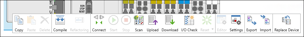
Right-clicking a device displays the different buttons of the context menu (see explanation under Context menus).
The Device Detail view has a tab for the input/output process image, as well as a tab for the data point configuration for Modbus, CANopen and other fieldbusses.