I/O Mapping
I/O mapping is the assignment of input, output, and memory addresses of the controller to program variables that are used by the application.
The display refers to the selected I/O module in the Device Detail view. If several I/O modules are selected, the I/O mapping of the last selected I/O module is displayed.
Column | Value (example) | Description | |
|---|---|---|---|
Variable | „Input01“ | Input field for the name of the variable to be used for mapping the channel in the CODESYS application. Double-clicking the input field displays the […] button for opening the Input Assistant. | |
Mapping |
| Symbol which displays a new or existing variable. | |
| The variable is not yet available, is newly created and can then be used in the entire project. | ||
| Uses an already existing variable for mapping | ||
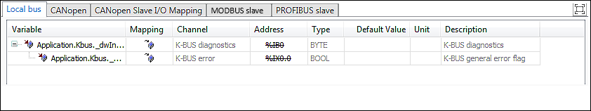
Channel | “Input channel 1” | Displays the symbolic name of the channel. | |
Address | „%IB3“ | Displays the address of the channel in the following format: %<Speicherbereich><Datentyp><Nummer(n)> | |
Memory area: | |||
I | Input/input memory area | ||
Q | Output/output memory area | ||
M | Marker memory area | ||
Data type: | |||
X | Single Bit | ||
None | Single Bit | ||
B | Byte (8 Bit) | ||
W | Word (16 Bit) | ||
D | Double Word (32 Bit) | ||
For additional information on I/O mapping and addressing, see the CODESYS Online Help, “I/O Mapping”. | |||
Type | „BYTE“ | Displays the channel data type The table cell remains empty if non-IEC data types are involved | |
Default Value |
| Default value of the variable | |
Unit | „ms“ | Displays the unit of the parameter value | |
Description | “Process data input channel 1” | Writes the parameter Edit the entry by double-clicking the entry field. | |

