Modbus Data Point Configurator
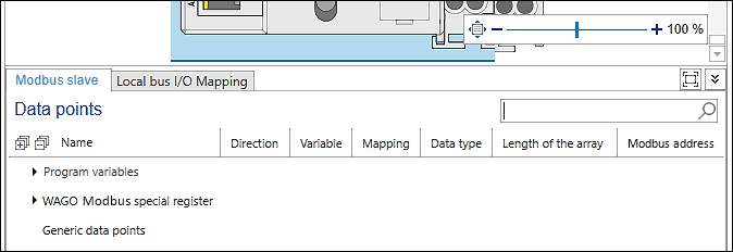
The Modbus data point configurator is displayed in the “Modbus slave” tab in the device detail view of the respective device.
The slave data points accessible via Modbus are created and configured in the Modbus data point configurator. The data points are available for all masters.
Like in the Modbus fieldbus configurator, the data points are also displayed in groups here. They can also be configured in the data point configurator.
Parameters | Description | ||
|---|---|---|---|
Name | Name of the Modbus data points Data points are displayed in group: | ||
Modbus Special Register | Predefined Modbus data points of the WAGO devices for configuration and diagnostics of the device | ||
Generic data points | If used to access existing data points in a certain way (using function codes) that represent any position in the existing Modbus process image Note: Generic data points cannot be accessed from the application. For this, the “Program variables” described below must be used. | ||
Program variables | Data points are displayed and created. Note: Only use [Add from Program] for program variables and not for variables from I/O modules. Such access is not possible. For I/O modules, use the alternative described by adding new data points and then assigning them from the application. | ||
Local bus data points | Data points that result from the hardware or from attached I/O modules | ||
Direction | Indicates whether it is input data or output data | ||
Input | The value of the variable is set exclusively via the fieldbus and is readable in the program. Write access in the program does not make sense because the value is constantly overwritten from the outside. | ||
Output | The value of the variable is set in the program and is only readable from the outside. | ||
Input / Output | The value of the variable can be read/set by the fieldbus as well as by the program. Note: If you only use the variable for the visualization as Input/Output, then make sure to select the option “Always update” in the “Settings” panel, “Modbus master” tab under “Updating variables”. Otherwise the variables are not updated in the visualization. | ||
Variable | Name of variable The name is always identical to the name of the program variable | ||
Mapping | Displays which variable is new and which variable already exists: | ||
| The variable is not yet available, is newly created and can then be used in the entire project. | ||
| An existing variable is used for mapping. | ||
Data type | Displays the data type of the Modbus data point and corresponding to the program variable The following data types are supported: | ||
• BOOL | • ARRAY OF BYTE | ||
Length of the array | Displays the number of elements for arrays | ||
Modbus address | Displays the Modbus address of the variable – bit-based (coil) or register-based | ||


Individual values of a line row, e.g., data point names, can be changed by double-clicking on the respective entry. Note that no points “.” in the name.
The Information icon (“i” in a blue circle) indicates that there are addressing overlaps. In other words, multiple data points are using the same tab. Double-click to adjust the tab.
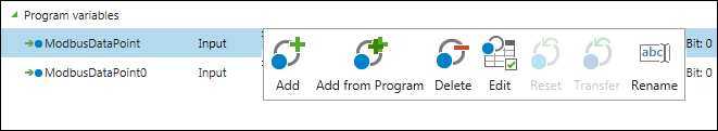
To create or edit a new data point, the following functions are available in the context menu (right-click on a line):
Symbol | Button | Description |
|---|---|---|
| [Add] | Adds a Modbus data point |
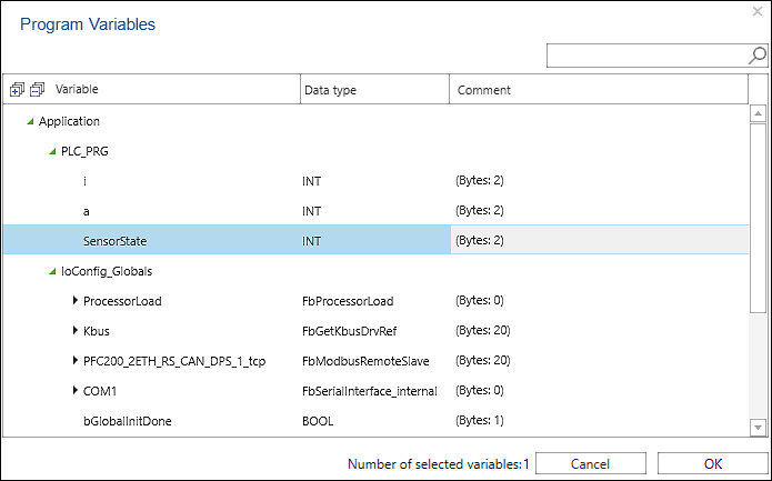
| [Add from Program] | Adds Modbus data points that represent variables of a controller program
One or more existing variables from the application or global variables from the project library can be selected that are to be published via Modbus. [OK] adds the variables in the Data Point Configurator. [Cancel] closes the dialog. Note: Simple data types are transferred directly via Modbus, while complex data types (including structures) are mapped to word arrays. These are then transmitted via Modbus. If the data type used is known globally in the project, the master can directly access the individual elements of the complex variables, although Modbus does not use such a data type itself. |
| [Delete] | Deletes the Modbus data point |
| [Edit] | Opens a dialog with further options (see description in the table below) |
| [Reset] | The button can be selected if a name has been changed. The name of the mapping variable is reset to the default (data point name). |
| [Transfer] | The button can be selected if a value has been changed (e.g., “Input” to “Output”) and then multiple rows have been selected. Clicking [Transfer] applies the value to all selected rows. |
| [Rename] | The button can be selected if the data point configurator has been called up for the slave device and there is a connection to another device. Clicking [Rename] opens a dialog to rename the variable. |


The [Edit] button is used to display a dialog with further setting options. Depending on the group (“Modbus special register”, “Generic data points” or “Program variables”), the setting options differ.
Parameters | Description |
|---|---|
Explicit access | Excludes the variables from any optimizations of the Modbus master |
Function code (read) | Function codes for reading the variables |
Address (read) | Address for reading the data point in the Modbus process image |
Function code (write) | Function codes for writing the variables |
Address (write) | Address for writing the data point in the Modbus process image |
Modbus address | If available: Bit-based (coil) or register-based access of the master setting |