Example Project: Creating a New Modbus Project in CODESYS
In this example, you will create a Modbus project with two PFC200 750-8212 Controllers, which are to be used the Modbus master and Modbus slave. You will add I/O modules, create a small program and exchange data between the devices.
Initial state:
- The 750-8212 Controllers have firmware version 23.
- You need to have installed CODESYS and required components, such as device descriptions and libraries (see 8 Installing and Launching).
Create the Project
- Click New Project on the start page or the “File” tab.
- Select the “Standard Project” as the template and assign a name for the project.
- The “Standard Project” dialog shows all the available devices. The devices result from the installed device descriptions.
- Select the first controller (in this example, a PFC200 750-8212) and the programming language you want to use.
- To add I/O modules, right-click on the “Kbus” element in the device tree and select Insert Device.
- Select the I/O modules of the node from the list and click [Insert Device] for each I/O module. In this example, the 750-430 and 750-530 I/O modules are used.
- The I/O modules of the node are attached below the “Kbus” element.
- To add the second controller to the project, right-click on the project name (the first element of the device tree) in the device tree and select Insert Device.
- Repeat steps 4 and 5 for this controller.
Connect to the Device
- To connect to the controller, double-click it in the device tree.
- In the graphical view consisting of the PC, gateway and device, enter the IP address of the controller – for example, 192.192.168.1.17 in this case – for the controller that is locally connected to the PC.
Alternatively, click [Scan Network] to search the network for devices.
Tip: To be able to identify the device more easily during a network scan, it is useful to define a unique host name for the device beforehand via the WBM. - Select your device and transfer it by clicking [OK].
- The login screen of the device opens.
- Log in to the device with your access data (default: user “admin,” password “wago).”
- Repeat steps 1 to 5 for the second controller.
Configure the Slave Device
- First create an “Ethernet” fieldbus element for the controller that is to be used as the slave. To do so, right-click on the device and select Add Device ....
- Select the “Ethernet” fieldbus under “Ethernet Adapter.”
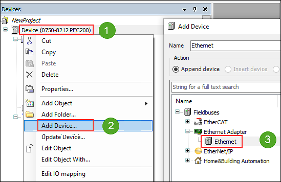
- Click [Add Device] and leave the dialog open.
- A new “Ethernet (Ethernet)” element is created in the device tree.
- Click on the new element and select the “Modbus TCP Slave” for the slave device under “Modbus” in the dialog that is still open.
- Confirm with [Insert Device].
- In what follows, you will create variables and write a short program to test the data exchange between the master and slave:
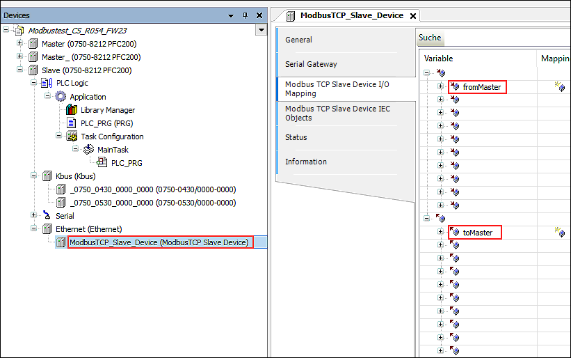
- Create Variables: Double click on the slave device to open the configuration.
- Create two variables on the “Modbus TCP Slave Device I/O Mapping” tab: one with the name “fromMaster” in the holding register and one with the name “toMaster” in the input register.
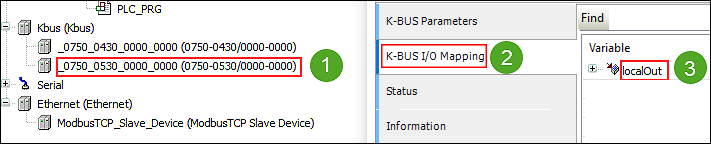
- To output variables to the I/O modules, double-click on each I/O module:
For the 750-430 Digital Input Module, enter “localIn” as the variable.
For the 750-530 Digital Output Module, enter “localOut” as the variable. 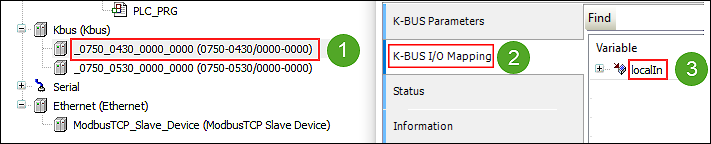
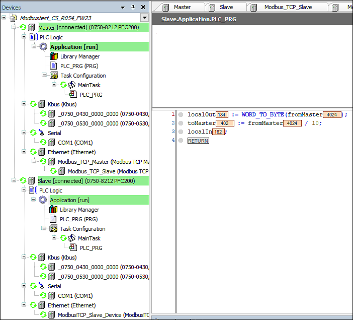
- Write the Slave Program: To open the program editor, double-click on the “PLC_PRG” slave program in the device tree.
- Create a simple program:
localOut := WORD_TO_BYTE(fromMaster);
toMaster := fromMaster / 10;
localIn;
The variable value sent from the master to the slave is output once on the I/O module as a test, divided by 10 and sent back to the master. - To compile the program, click Generate Code on the “Build” tab (alternatively: function key F11).
Configure the Master Device
- Create an “Ethernet” fieldbus element for the controller that is to be used as the master. To do so, right-click on the device and select Insert Device ....
- Select the “Ethernet” fieldbus under “Ethernet Adapter.”
- Click [Insert Device] and leave the dialog open.
- A new “Ethernet (Ethernet)” element is created in the device tree.
- Click on the new element and select the “Modbus TCP Master” for the master device under “Modbus” in the dialog that is still open.
- Confirm with [Insert Device] and leave the dialog open.
- Click the new “Modbus_TCP_Master (Modbus TCP Master)” element in the device tree and insert the “Modbus TCP Slave Device” element from the dialog that is still open.
- It is placed in the device tree below the Modbus master and represents the slave device.
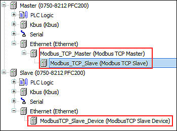
- To link the master and slave, now enter the IP address of the slave device for the “Modbus_TCP_Slave (Modbus TCP Slave)” below the master. To do so, double-click “Modbus_TCP_Slave (Modbus TCP Slave)” to open the configuration and enter the IP address of the slave device on the “General” tab.
- Click the “Modbus Slave Channel” tab and create two channels, which you will use these to specify where and how much to read/write.
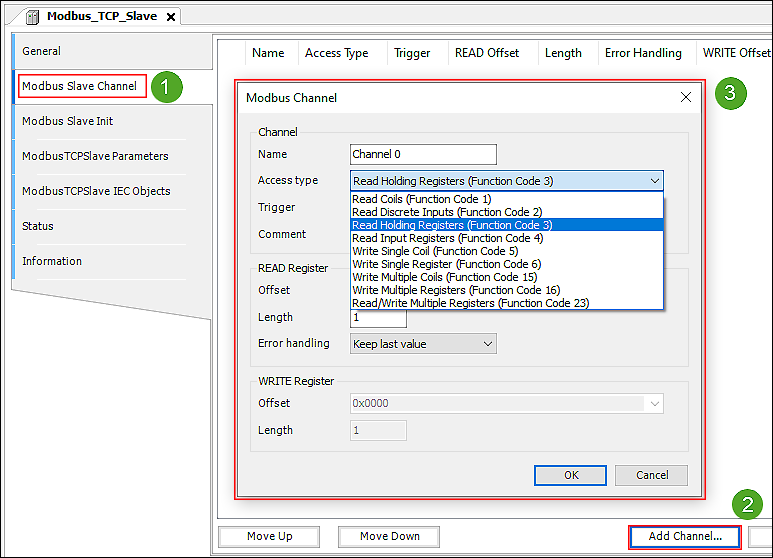
- Your choice of the access type (or Modbus service) and offset for addressing on what your slave supports. Selecting function codes 4 and 16 is often useful for reading and writing multiple values. For more information about supported Modbus services, refer to the manual of your slave device.
In this example, one channel is created with “WriteSingleRegister” and one channel with “ReadInputRegisters,” since only one value is read and written in this case. - Click the “Modbus TCP Slave I/O Mapping” tab and create two variables here: “toSlave” (WriteSingleRegister) and “fromSlave” (ReadInputRegisters).
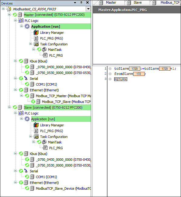
- Write the Master Program: To open the program editor, double-click on the “PLC_PRG” master program in the device tree.
- Create a simple program:
toSlave:=toSlave+1;
fromSlave;
One variable value is incremented and one is output. - To compile the project, click Generate Code on the “Build” tab (alternatively: function key F11).
Connect the Master and Slave Applications Online
- To connect the application, right-click “Application” for the master and slave respectively and select [Login].
- For each, download the program to the device.
- Launch the application by right-clicking “Application” and Start.
- The program is now running.