EtherNet/IP – First Steps
- Add a controller that is to be used as an EtherNet/IP master (scanner) to your project.
- Import the EDS file of a slave device (adapter) via the “Tools” tab > “Device Repository.”
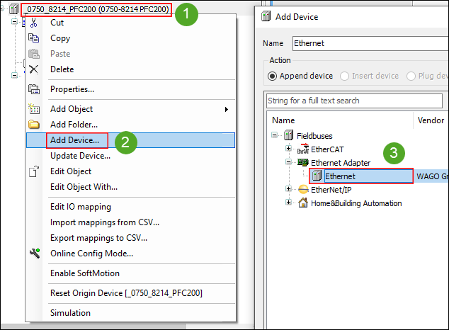
- Right-click on the controller and click Insert Device ....
- Select the “Ethernet” item under “EtherNet/IP” > “EtherNet/IP Adapter” and click [Insert Device].
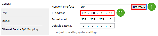
- Double-click the “Ethernet (Ethernet)” element to configure the Ethernet interface.
- On the General tab, click [Browse ...], select network adapter “br0” and enter the IP address for the EtherNet/IP interface.
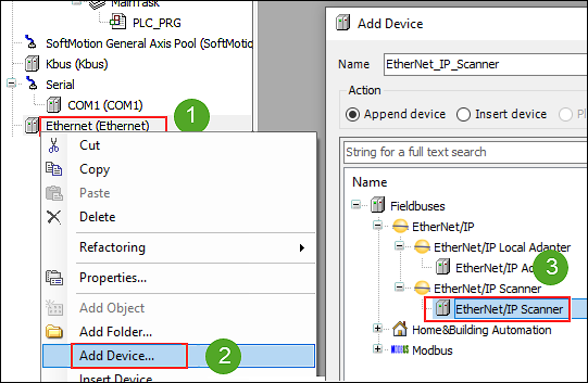
- In the device tree, right-click “Ethernet (Ethernet)” and select Insert Device ....
- Select the “EtherNet/IP Scanner” under “EtherNet/IP.”
- Select Insert Device ... and leave the dialog open.
- Click on the “EtherNet_IP_Scanner (EtherNet/IP Scanner)” element in the device tree and select the slave device (adapter) imported via the EDS file in the dialog that is still open.
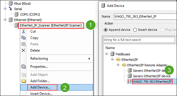
- Click [Insert Device].
- Double-click on the slave device in the device tree to open the slave configuration and specify connections and assemblies.
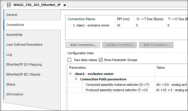
- In EtherNet/IP, I/O data (input and output data points) is transferred via so-called connections (the term “Connections” is also used in e!COCKPIT). When the fieldbus starts up, one or more of these connections can be established between an EtherNet/IP master and an EtherNet/IP slave. The input and output data points of a connection and the configuration data are grouped into so-called assemblies. To see which connections a slave device supports, consult the device description file (EDS file) or the respective product manual of the slave. The connections and the data to be transferred are usually configured automatically using the information contained in the EDS file.
- On the “Connections” tab, use [Add Connections ...] to create new connections according to your product manual.
- Click on the new connection and then click [Edit Connection ...] to set the path in the dialog and to set or change the size of the input/output data (T → O / O → T) for your connections.
- Click the Assemblies tab to see how the assemblies were created according to your input/output data.