Project conversion using the example of Modbus
Initial state:
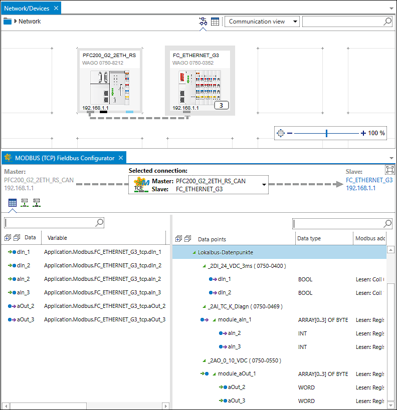
In this example, an e!COCKPIT project is converted, consisting of a PFC200 (750-8212) as the master with a connected CANopen coupler (750-352) as the slave. There are three I/O modules plugged into the coupler: a 2-channel digital input module (750-400), a 2-channel analog input module (750-469) and a 2-channel analog output module (750-550). You can see the data points of these three I/O modules in the fieldbus configurator under “Local Bus Data Points.” These data points were mapped to master variables by dragging and dropping them.
In brief:
In the following description, you perform the following steps in CODESYS: You delete the slave device and update the master device. Global Modbus variables are retained. You then recreate the Modbus structure with the master and slave in the device tree and recreate the I/O image (channels, length of input/output data depending on I/O modules). You then reassign the existing global Modbus variables.
- First delete the slave device. It contains no data you will need.
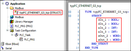
- The required Modbus variables are generally created globally. In the device tree under “Application” > “Modbus,” you will find a structure that shows these globally stored variables:
- For the new slave that you will create, you will reuse these variables and assign them to the input/output data of your I/O modules in CODESYS.
- First, right-click on the device and select Update Device ... to load the device description for the device.
- Select your device from the list and click the [Update Device] button.
- The fieldbus elements are removed. However, the global variables are retained.
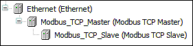
- Now recreate the master and the slave. To do so, right-click on the device and select Insert Device ....
- Leave the dialog open for the next three steps and click [Insert Device] to insert the “Ethernet” fieldbus, as well as the master and the slave inserted below it:
- First select the “Ethernet” fieldbus in the dialog.
- Click on the new “Ethernet” element in the device tree and select the Modbus master in the dialog.
- Click on the new “Modbus_TCP_Master” element in the device tree and select the Modbus slave in the dialog. - This procedure creates the following structure in the device tree:
- Double-click on the slave (“Modbus_TCP_Slave” element).
- The configuration opens.
- Click “Modbus Slave Channel” and click the [Add Channel ...] button there on the bottom right.
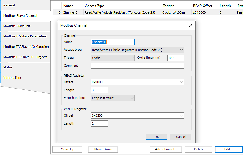
- Set the channel, access type and length for reading and writing according to the I/O modules you use.
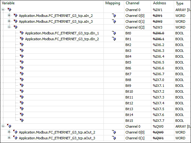
Here, for example, the “READ Register” is set to a length of 3 (one 2-channel DI + one 2-channel AI) and the “WRITE Register” to length 2 (2-channel AO). - Click “Modbus TCP Slave I/O Mapping.”
- You now see the channel and variables that were created. You will remap/reassign the global variables of the I/O modules to these.
- To do so, in the corresponding variable field, click the [...] button that appears to the right to open the Input Assistant.
- Under “Application” > “Modbus” > “FC_ETHERNET_G3_tcp,” you will find the global variables for selection.
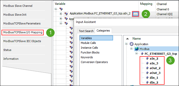
- Go through these one by one to recreate your slave from the e!COCKPIT project in this way.
- This completes the conversion.
 Note
Note
Please note the following restrictions in CODESYS as opposed to e!COCKPIT:
• Modbus RTU and UDP are currently not supported in the configurator. However, you can use MODBUS functions for RTU and UDP via the IEC library “WagoAppPlcModbus”.
• Specific TCP/IP parameters (Keep Alive, Type of Service) are not supported.
• Function code FC22 (masking of registers) is not supported.
• Nor is function code FC66 (polling of larger amounts of data in one request).
• Device-specific special registers are not supported.
• The MODBUS service is only available when the PLC application is running.