Project Conversion on the Example of EtherNet/IP
Initial state:
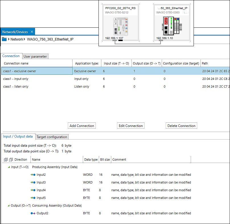
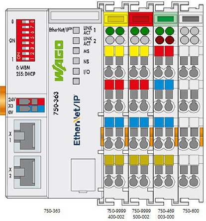
In this example, an e!COCKPIT project consisting of a PFC200 (750-8212) and a coupler (750-363) connected via EtherNet/IP is converted. An analog input module, a digital input module and a digital output module are plugged into the coupler; this yields an input data size of six bytes and an output data size of one byte. Variables corresponding to these data sizes have been created in the lower area of the Data Point Configurator. In the fieldbus configurator, the variables have been mapped to data points.
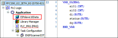
Important: A global variable list has been created in e!COCKPIT for the input/output data so the data will be retained in CODESYS throughout the update (Program Structure > right-click on “Application” > “Global Variable List”).
In brief:
In the following description, you perform the following steps in CODESYS: You update the device and create an Ethernet fieldbus under the device. You attach an EtherNet/IP scanner to it and the EtherNet/IP device below it. You adjust the EtherNet/IP connection and the length of the input/output data. Then you assign the address for each variable according to the hardware, and you can continue using your project.
- First delete the slave device (in this case: 750-363). It contains no data you will need.
- Right-click on the PFC200 and select Update Device ....
- Select your device (in this case: 750-8212) and click [Update Device].
- EtherNet/IP is removed from the tree. However, the variables you saved globally in e!COCKPIT are still available.
- Now recreate the master and the slave. To do so, right-click on the PFC200 and select Insert Device ....
- Leave the dialog open for the next three steps and click [Insert Device] to insert the “Ethernet” fieldbus, as well as the master and the slave inserted below it:
- First select the “Ethernet” fieldbus in the dialog.
- Click on the new “Ethernet” element in the device tree and select the “EtherNet/IP Scanner” in the dialog under “EtherNet/IP.”
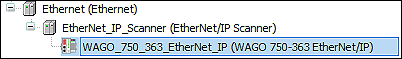
- Click the new “EtherNet_IP_Scanner (EtherNet/IP Scanner)” element in the device tree and select the EtherNet/IP device 750-363 in the dialog under “EtherNet/IP Remote Adapter.”
If you do not see the EtherNet/IP device in the list of selections, then you must first install the corresponding device description; see 8 Installing WAGO Device Descriptions separately. - This procedure creates the following structure in the device tree:
- Double-click the EtherNet/IP adapter to make further settings:
- To enter the IP address of the device, open the “General” tab.
- To adjust the EtherNet/IP connection, open the “Connections” tab.
- Double-click on the connection that was automatically created before and enter the data length of your input/output data:
• Scanner to target (output) = data length of the output modules (in this case: one byte)
• Target to scanner (input) = data length of the input modules (in this case: six bytes) 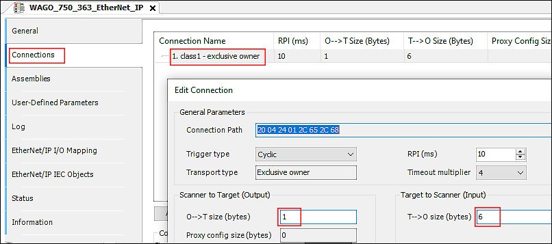
- Click [OK] to confirm.
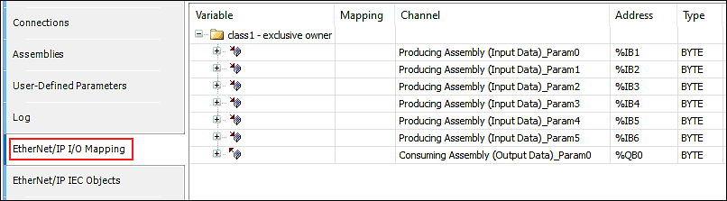
- Under “EtherNet/IP I/O Mapping,“ you can now see the input/output variables that have been created with the required size. No variables for the respective input/output data of the I/O modules are assigned here yet. You will perform the mapping in what follows.
- First take a look at your hardware configuration to see which I/O module is the first I/O module to be addressed at the node and what data length it occupies. The representation of the node in WAGO I/O-CHECK can be helpful for this purpose.
- Switch to the global variables (cf. item 3).
- Click on a variable and press [Shift] + [F2]. This opens the variable declaration dialog.
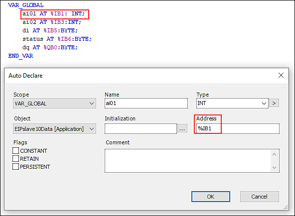
- Now enter the addresses for the input/output variables of the I/O modules in order according to your hardware structure:
In this example:
• Analog input starting from byte 1 – address %IB1 → occupies two bytes
• Analog output starting from byte 3 – address %IB3 → occupies two bytes
• Digital input starting from byte 5 – address %IB5 → occupies one byte
• Status byte starting from byte 6 – address %IB6 → occupies one byte
• Digital output starting from byte 0 – address %QB0 → occupies one byte
- Represent your hardware in this way.
- The full scope of the program can then be used.