Connect Controller (Master) to Fieldbus Coupler (Slave)
In this example, you will set up a network consisting of a PFC 750-8216 as the EtherCAT master and two EtherCAT couplers 750-354 as slaves.
Place Devices in the Topology View
- First, open the Network view in the Topology view.
- Note: First carry out your configuration completely in the topology view because the physical connection results in topology information that is required for addressing EtherCAT devices (automatic calculation of auto-increment addresses).
Always make sure that you completely configure both topology and communication views. If there are inconsistencies in the addressing, check the order in which the slaves are connected to the master (EtherCAT Fieldbus Configurator > “Sync-Unit Mapping” tab) and compare them with the assigned auto-increment addresses (interface settings of the respective slave). In case of doubt, establish the connects between devices again. - Select the controller, 750-8216 here, from the product catalog and drag it into the Network view (Topology view).
- Add two 750-354 EtherCAT fieldbus couplers.

Disconnect Ethernet Ports and Enable EtherCAT Port
- Select the controller to be configured as the EtherCAT master.
Note: The controller must be accessible online for the following settings. - Open the “Settings” control panel.
- Set the IP address in the “Device” tab.
- The Ethernet ports of the device are set to Switch function by default. To use one of the ports for EtherCAT, disconnect the ports first.
- Click the [Settings] button in the same tab.
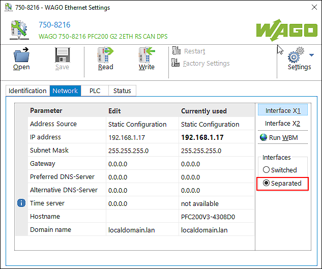
- The integrated “WAGO Ethernet Settings” tool opens.
- The “Network” tab is on the right side in the “Interfaces” area.
- Select the “disconnected” option.

- Click the [Write] button.
- If the write operation is completed, the X2 interface is now also released for configuration in addition to the X1 interface in the “Network” tab that is still open.
- Click [Interface X2 ] and change the IP address for the EtherCAT port on the left side if needed. Otherwise, the default address is used.
- Check if “e!RUNTIME” is set as the runtime system in the “PLC” tab in order to configure the device via e!COCKPIT.
- Click the [Write] button.
- When the write operation is completed, close the window.
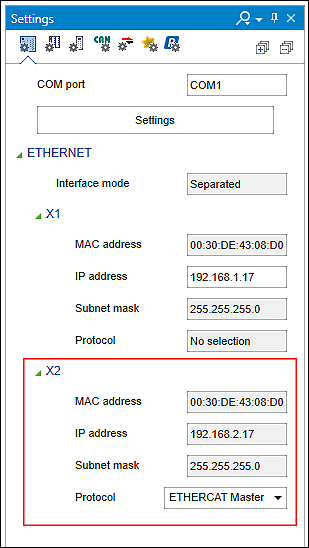
- The display expands in the “Settings” control panel, “Device” tab.
Both ports are now displayed with the respective IP information. - Select the “EtherCAT Master” setting in the “Protocol” selection field for the “X2” interface.

- A dialog informs you that the EtherCAT master functionality requires a license.
- Click [Yes] to confirm the message.
- The EtherCAT port is enabled.
 Note
Note
Establishing a connection with disconnected interfaces only possible via X1!
If you have set separate interfaces in “Ethernet Settings” (Network > Interfaces > “disconnected”), only the X1 interface can be used to establish a connection from e!COCKPIT to the device. This is the case, for example, when using the “EtherCAT” fieldbus.
You do not need to assign any IP addresses for communication with the EtherCAT slaves, as EtherCAT uses its own addressing.
Disable the Broadcast Protection Function
EtherCAT works exclusively with broadcast messages. Therefore, the broadcast protection function must be switched off in the controller if the EtherCAT master is used. You can do this, for example, from the WBM.
- Open the WBM page “Ethernet Configuration”.
- In the “Switch Configuration” group, find the “Broadcast Protection” selection field and select “Disabled”.
- Click the [Submit] button to apply the change.
Connect Devices
- Connect the master to the slaves via EtherCAT connectors.

- The EtherCAT devices are addressed automatically in the order of their configuration.
- Switch to Communication view.
- Connect the devices to each other.

- A yellow warning icon in the in the device tile of the master indicates that a license is required to use the EtherCAT Master functionality.
- You can run the device without a license for 30 days in evaluation mode. Otherwise, follow the steps below.
Use License for Master
- If you have already purchased a license, first enter it in e!COCKPIT: Backstage View > “Licensing” page, [License Management] > [Enter Licenses].
- Once you have entered the license, open the “Available Licenses” and “Project Licensing” panels (via the ribbon > “VIEW” tab >[ Available Licenses] button and [Project Licensing]).
- Use the “Automatically Assign All” option on the “Project Licensing” panel (recommended).
Alternatively, drag the license from the “Available Licenses” panel to the appropriate device on the “Project Licensing” panel, or drag the license directly onto the device in the Network view. - Then load the license onto the device by synchronizing it (the [Synchronize] button on the DEVICE tab of the ribbon or on the “Project Licensing” panel).
- The yellow warning icon disappears. The licensed EtherCAT Master functionality can be used without limitation.
 Note
Note
Information about licensing in the e!COCKPIT product manual:
The e!COCKPIT product manual describes in detail how licensing is handled. It describes how to acquire licenses, activate them, assign them to devices and link them in the device (see “Acquiring Licenses,” “Activating Licenses” and “Activating Runtime Licenses” in the e!COCKPIT product manual).
Make the Device Settings on the “Settings” Panel
You can find the settings for the EtherCAT master and the EtherCAT slave in the “Settings” control panel > “EtherCAT” tab by clicking the [Interface Settings] button.
EtherCAT Master
The Master interface settings do not have to be adapted for standard EtherCAT networks.
The “Autoconfig Master/Slave” and “Select network by name” settings are set by e!COCKPIT automatically. In addition, the EtherCAT bridge “br1” (identifies port X2) is permanently set as the “Network name”.
Recommendation: To remain device-independent, do not enter a fixed MAC address. Instead, use network names as default to identify devices in the EtherCAT network.
EtherCAT Slave
The Slave Interface Settings do not have to be adapted for standard EtherCAT networks.
At the top, you see the AutoInc address of the respective slave that is due to the topology and is generated automatically. Communication via EtherCAT takes place via this address.
Optional: Enable Expert settings to show other settings at the bottom. The setting also ensures that two additional “Process Data Expert Mode” Tab and “Online” Tab tabs are displayed in the EtherCAT fieldbus configurator. You need the “Online” tab, for example, for firmware update settings (see also Update Firmware for EtherCAT Devices (“FoE”)).
Configure Slave
You configure the slaves in the data point configurator.
- Double-click a slave to configure it.
Note: To configure the slave, it must be offline. - A tree structure is displayed at the top of the window that initially includes only the slave.
- Add the slave modules from the product catalog.
- Tip for finding devices:
If device descriptions apply to multiple devices, the name of the device description can contain one or more “x”. When searching for “750-530”, for example, the relevant device description “750-5xx” is not found. In this case, orient yourself in the search at the corresponding folders, e.g., “Digital Input”. - Optional: You can set the start parameters for each device at the bottom of the Data Point Configurator.
Note that you have to enter the “Value” parameter in the table and dialog window in decimal.
If you have disabled the “Autoconfig Master/Slaves” option in the interface settings of the master (“Settings” control panel > “EtherCAT” tab > [Interface Settings]), the “FMMU/Sync” tab displays with settings for FMMU and synchronization managers in addition to the “Start Parameters” tab. These are Expert settings that are not required for standard applications.
Configure Connection between Master and Slaves
- Open the EtherCAT Fieldbus Configurator by clicking the EtherCAT connector of one of the devices or the connection and selecting [Configurator] in the context menu.
- You see the same tree structure on the right that you have previously configured.
- If you select a device or module here, then the relevant process data is displayed on the left in a context-sensitive manner.
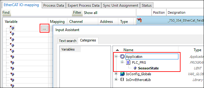
- In the “Variable” column, map to IEC variables that you already use in your application (example “SensorState”).
Tip: Use the input assistant by double-clicking […] or pressing [F2]. 
- Switch to the “Program Structure” control panel.
- You can now access the slave variable in your application that you mapped to the master variable previously.
Change Routing Settings (Optional)
Provided your device supports “Ethernet over EtherCAT” (EoE) and the expert settings are enabled in the slave's interface settings, the “EoE” Tab is displayed in the fieldbus configurator. You can change communication settings for the individual slaves in order to exchange data tunneled from an Ethernet network into the EtherCAT network, to call up the integrated Web server or to enable access to external engineering. Installation of the required interface for the controller (TAP device), routing and configuration are described at Reach EtherCAT Slaves via Ethernet (“EoE”).
Test the Connection
- Right-click on the master and select [Connect].
- Log into the device.
- Download the application.
- If the device is connected online, you can check the EtherCAT fieldbus status in the device tooltip.
Diagnostics messages of the device are available in the interface settings (“Settings” control panel > “EtherCAT” tab > [Interface Settings]) and in the EtherCAT Fieldbus Configurator > “Status” tab.