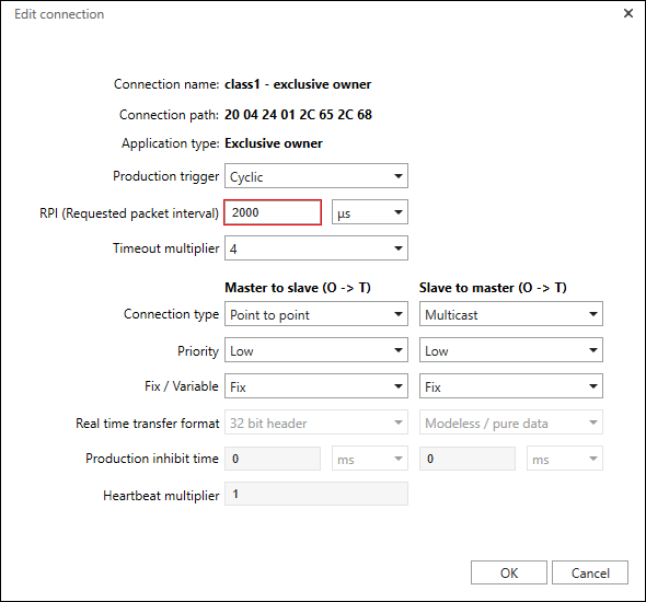
Editing a Connection
The [...] button to the right of the connection name opens the “Edit Connection” dialog for adjusting the connection settings.

Parameter | Description | |
|---|---|---|
Connection Name | Shows the name of the connection (Changes to the connection name are made in the data point configurator > [Edit Connection] > Adding and Editing a Connection dialog). | |
Connection Path | Specifies the addressed assembly instances that hold input data and receive output and configuration data (Changes to the connection path are made in the data point configurator > [Edit Connection] > Adding and Editing a Connection dialog). | |
Application Type | Shows the application type according to the EtherNet/IP standard (Changes to the application type are made in the data point configurator > [Edit Connection] > Adding and Editing a Connection dialog, but are only possible connections you created yourself). | |
Production Trigger | Defines how the data exchange is triggered: | |
Cyclic | Message transfer is triggered periodically at a specific recurrence interval (packet rate). | |
Change of State | Message transfer is triggered by the change of a specific state. | |
Application Object Triggered | Message transfer is triggered by the application. | |
RPI (Request Packet Interval) | Transmission interval for data packets in ms or µs Within this time interval, the sending application requests transfer of data to the target application. | |
Timeout Multiplier | Timeout multiplier × 4, 8, 16, 32, 64, 128, 256, 512 If a device fails, the system waits for the RPI time × the timeout multiplier before the device enters the error state. | |
Master to Slave (O → T) | Communication directions | |
Connection Type | Sets the connection type | |
Multicast | T → O: The slave sends the data to multiple subscribers. | |
Point-to-Point | The slave sends data to exactly one master (T → O) or receives data from exactly one master (O → T). | |
Priority | Sets the priority of the connection | |
Low | Low priority | |
High | High priority | |
Scheduled | The network-specific connection priority is used. | |
Urgent | The network-specific connection priority is used. | |
Fixed/Variable | Sets how the connection data relates to the assembly sizes Note: For more information about parameters, see the EtherNet/IP CIP specification, volume 1 and volume 2. | |
Fixed | The amount of data transferred by the connection must correspond to the assembly sizes. | |
Variable | The amount of data transferred by the connection must be <= the sizes of the assemblies. | |
Real-Time Transfer Format | Sets a real-time transfer format | |
32 Bit Header | Note: The real-time transfer format is usually fixed for a connection. If it is not, use the settings specified in the product manual of the device. | |
Zero Length Data | ||
Modeless | ||
Heartbeat | ||
Production Lock Time | Specifies the minimum time before new data is transmitted in ms or µs The production lock time is used to reduce data transfer on the network during transmission. The production lock time can be set if the production trigger is non-cyclic, i.e. set to “Change of State” or “Application Object Triggered.” In contrast, for cyclic transmission, the RPI specifies the transmission interval. Note: Note that not every slave device supports lock times. | |
Heartbeat Multiplier | Limits the number of heartbeat signals from the master to the slave (O → T) to every xth time The heartbeat multiplier is used to reduce the data transfer on the network. The heartbeat multiplier is configurable if the real-time transfer format for the O → T transfer direction is set to “Heartbeat.” Example: If the heartbeat multiplier is set to “5,” the master only sends a heartbeat signal every fifth time. With cyclic data exchange, that would mean the heartbeat signal is sent every fifth cycle. The default setting is “1.” This means the signal is sent every time. | |