Performing a Systematic Input/Output Test (I/O CHECK)
Check for correct wiring of your node using the systematic input/output test. You can test both individual modules and entire nodes.
Testing Individual Modules:
- Open the Device Detail view.
- Click a module.
- Click the [Create] button in the “IO-CHECK” tab of the menu ribbon
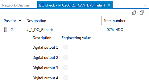
- A tab is opened in the workspace, in which the selected module is displayed.

- To add additional modules to this test, repeat steps 1–3.
Testing an Entire Node:
- Open the Network view.
- Click a device.
- Click the [Compile] button in the “IO-CHECK” tab of the menu ribbon.

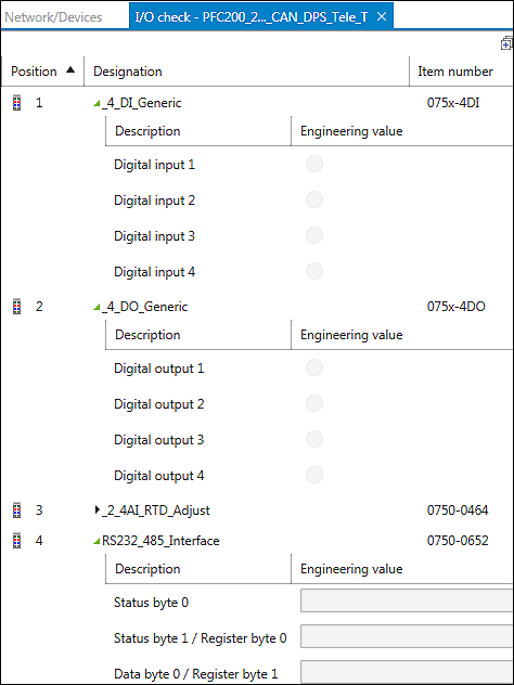
- An overview of input/output channels of the corresponding modules is displayed in both cases.
- Click the [Connect] button in the menu ribbon.
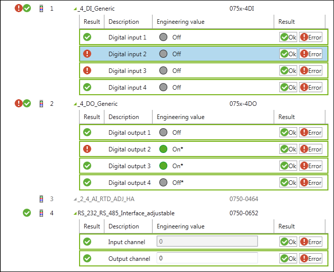
- The monitoring function is active first. The current values are displayed. If required, the “Result” column can be switched on/off via the button of the same name in the menu ribbon.
- Compare the displayed values with your hardware, e.g., whether the green LED is actually lit and for each entry click either [Ok] or [Error].

- Depending on your entry, the status is shown in the “Result” column.

- Besides value monitoring, you can also write or read them.
- Switch to manual override mode by clicking [Manual override mode] in the menu ribbon.
- Change the individual values. For this use, the slide adjuster and entry fields for analog output terminals; for digital output terminals click, the LED symbol.

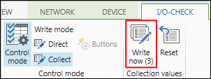
- Changed values are indicated with an asterisk (*) and the number of prepared changes shown as a number in the menu ribbon (here: 3) if “Collect” is active (blue background).
- To load all changed values to the I/O module click the [Write now] button in the menu ribbon. The write operation is performed once.

- If the [Direct] button is clicked, the values are continuously written as they are entered.
For additional information see:
- Menu Ribbon > “I/O CHECK” Tab