Connectors
Each device supports specific interfaces/protocols for communicating with other devices. The interfaces are shown as connection points (connectors) in different colors on the edge of a tile.
Connectors are displayed in the Communication view and in the Topology view. In the Communication view, they represent logical interfaces using protocols. In the Topology view, they represent actual connections to the device.
Connectors of the Communication View

Connector Color | Description |
|---|---|
Gray | Connector for ETHERNET based connections (e.g., Modbus or EtherNet/IP) and connections via activated port forwarding |
Black | Connector for serial connections/COM interfaces |
Blue | Connector for CANopen connections |
Purple | Connector for PROFIBUS connections |
Green | Connector for PROFINET connections |
Red | Connector for EtherCAT connections |
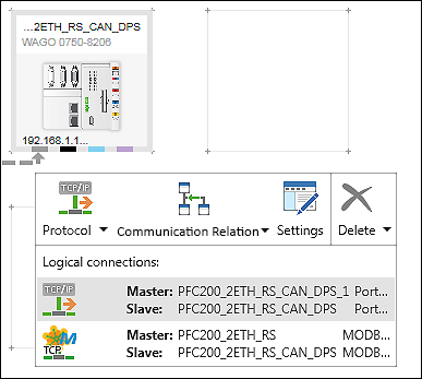
If the mouse touches a connector, the protocol of the interface is displayed, e.g., “ETHERNET”. If there are already connections to other devices via that interface, clicking on the connector opens a context menu with setting options that affect the connection.
Symbol | Button | Description |
|---|---|---|
| Protocol | Protocol of the logical connection If multiple connections are possible (e.g., Modbus (TCP) and Modbus (UDP)), the arrow symbol can be used to select them. If a device is already connected to multiple other devices, the connections appear in the context menu and can be selected by a mouse-click. The selected connection is dashed and highlighted in bold in the network view. The direction of the arrow of the connection is from the master to the slave. If a device can be used as a router for other devices, “Port forwarding” can be selected via the arrow icon. If port forwarding is selected, the [Configurator] button in the context menu changes to [Settings]. |
| Communication relation | Displays possible communication relationships between devices Device roles (master/slave) can be switched in this menu. Passing the mouse over the communication relationships displays the respective connection direction in the network view by a dashed line and an arrow. |
| Configurator
Or: | Opens the connection settings (see Configuration of Communication Connections). |
| Settings | Opens the “Settings” panel and displays port forwarding settings. The button is available if port forwarding has been selected for the device. |
| Update | Updates the configuration The button is available if the configuration for connected devices has been changed. Example: The configuration of a master device is adapted to the configuration of the connected slave. This is indicated by a warning icon above the respective connector of the tile. |
| Delete | Deletes the connection of the selected interface If multiple devices are connected via the interface, “Delete all connections” can also be selected via the arrow displayed |
 (z. B. für Modbus TCP


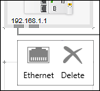
Connectors of the Topology View

Connector Color | Description |
|---|---|
Gray | Connectors for RJ-45 network connections via ETHERNET |
If the mouse touches a connector, name and symbol of the connection is displayed. Clicking the connector also displays the [Delete] button in the context menu. The button is used to remove the connection to other devices.