Scan View
Device/module scan can started in various ways:
- The “NETWORK” tab > [Scan] finds devices in the network.
- The “DEVICE” tab > [Scan modules] finds device modules.
- The context menu of a device > [Scan] finds device modules.
Triggering the scan opens a new “SCAN” tab. In the Network view, both devices already configured and scanned devices are displayed.
Deviations between the configured and scanned configuration are marked accordingly in color. The scan results can be applied completely or partially if desired.
 Note
Note
Apply devices to add them to the project!
Please note that displayed, scanned devices in the Network view are only applied to the project if you click [Accept selection]/[Accept all].
This is just a Scan view even if you see devices in the interface.
Scan Results in the Graphical Network View
The scanned devices are displayed in the Network view. Scanned devices are displayed below any already configured devices.
Each tile contains the device name (device type), manufacturer, item number and IP address as shown below in color.
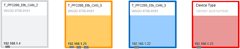
Color | Description |
|---|---|
Gray | Devices that are already configured (scanned device matches the configured device) |
Orange | Project devices that do not match the scan results (e.g., modified configuration) |
Blue | New devices |
Red | New and unknown devices (No matching device description was found to use the device. Contact Support. |
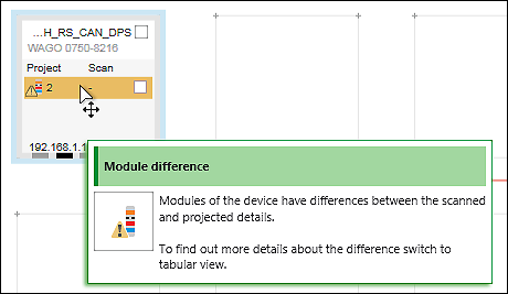
The configuration of an already configured device deviates from that of a scanned device, the differences appear in the tile:
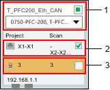
Pos. | Description | |
|---|---|---|
1 | DeviceType | Display of the device type If the device type is not clearly identified during scanning, i.e., multiple device types match, they are displayed in the selection field. |
2 | Connections | Display and comparison of device connections between the project (left) and scan results (right) The checkbox is used to apply the scanned connection to the project. Note: Connections are only displayed in the Topology view. |
3 | I/O modules | Display and comparison of the number of connected I/O modules between the project (left) and scan results (right) The checkbox is used to apply the I/O modules to the project. Note: Further details are displayed in the tabular view. |
More information regarding the differences is displayed in ToolTips if you move the mouse over the tile.
Physical Connections in the Topology View
In the Topology view, difference between configured and scanned connections for physical device ports are highlighted in color as shown below (the example below is a CANopen connection (light blue)):
View/Color | Description | |
|---|---|---|
| Connecting line in fieldbus color | Connection that matches in the configuration and scan |
| Connecting line in fieldbus color, but transparent | Old connection that is not (no longer) available in the scan results |
| Connecting line in fieldbus color, blue dashed lined | New connection |
| Connecting line in fieldbus color, orange dashed lined | Modified connection |


By clicking a connection in the tile, the respective connecting line is highlighted.
Applying Scanned Devices
Scanned devices, connections and/or I/O modules to be applied in the configuration must be selected by selecting the checkbox.
If you select the checkbox for the device (top right in the tile), the scanned device is applied with all connections and I/O modules. However, connections or I/O modules can also be enabled/disabled individually.
If the device type cannot be uniquely assigned when scanning, a selection field is displayed where you can select the required device type.
[Accept selection] or [Accept all] in the ribbon, “SCAN” tab is used to apply the selection from the scan results.
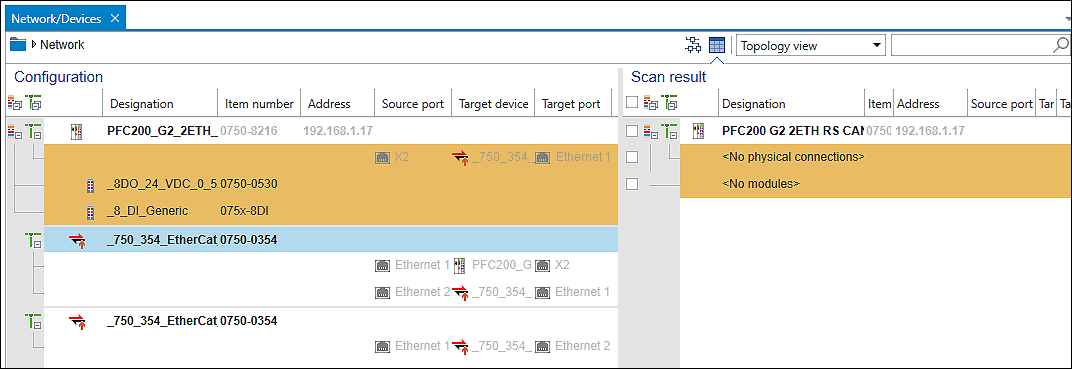
Scan Results in the Tabular Network View
The tabular Scan view is particularly useful for an overview if devices have differences in the I/O modules used.
The tabular Scan view provides an overview of configured devices on the left side and scanned devices on the right side. Modules and connections are displayed in hierarchical order under the respective device.
Similar to the graphical Scan view, device details are displayed and differences between project and scan are highlighted in color (see Table Color Coding in the Scan View).
You select devices, modules and connections to be applied by selecting the respective checkboxes on the right side and applied by clicking the respective buttons in the ribbon.
If the device type of a scanned device matches a devices that has already been configured, the scanned device can be dragged and dropped onto the configured device in this view and applied. Scanned I/O modules of a head station overwrite configured I/O modules.