Creating a Simple CANopen Network
In the following description you connect two CANopen devices and create data points for joint communication.
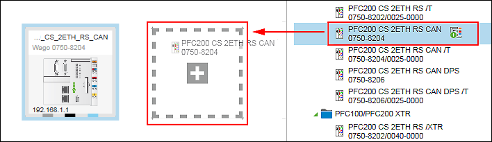
- Select two devices from the Product Catalog (e.g., 750-8204) and drag them with the mouse into the Network view (Communication view).
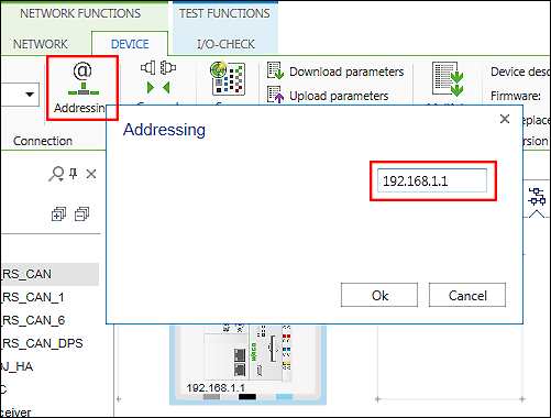
- Select the first device and click the “DEVICE” tab in the menu ribbon.
- Click the [Addressing] button.
- Enter the IP address of the device in the entry field and click [Ok].
- Proceed in the same way with the second device. The IP addresses of both devices must be different.
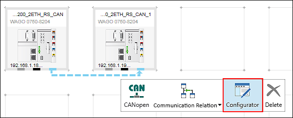
- Create a logical connection between the devices by dragging a connection from the CANopen connector of the first device to the CANopen connector of the second device.
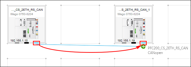
- By dragging the connection (direction matters), you automatically make device 1 the master and device 2 the slave.
- If you want to change the roles of the devices later, click the CANopen connector of one of the devices to open the context menu. Click [Communication Relation] in the context menu and change the direction of the connection (Master ← → Slave).
Preparing the Slave: - Select the CANopen slave with the mouse.
- Change if required the “Node ID” (e.g., “127”) and the baud rate (e.g., 250000) in the “Settings” panel, “CANopen” tab.
Note that node IDs within a CANopen network must always be unique. 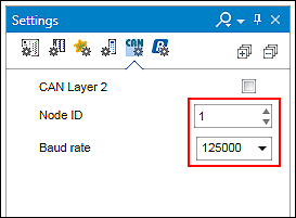
- Create a data point (UINT) for the slave in the CANopen data point configurator. Double-click on the CANopen slave.
- The Device Detail view appears. The CANopen data point configurator is displayed as a “CANopen” tab.
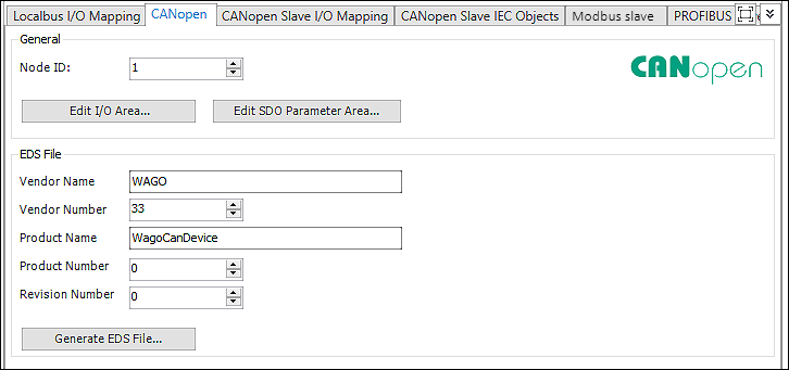
- To add a data point, click first the [Edit I/O area…] button in the “CANopen” tab.
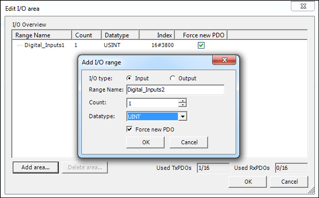
- Click the [Add area…] button in the following dialog.
- Enter the I/O type, name, number and data type of your data point and confirm via [OK]. Create several data types if required.
- Move to the “CANopen Slave I/O Mapping” tab.
- The created data points and your channels within the I/O range are displayed here. If the display is incomplete, close the tab and reopen it.
- Go back to the Network view (Communication view).
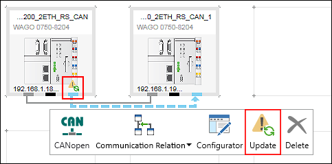
- The configuration of the slave was changed. This is indicated as a warning symbol (yellow triangle with an exclamation mark) above the connector of the device tile. The configuration must be updated in order for all created slave data points to be available in the master.
- Click the master connector and then [Update].
- In the “Choose Update Behavior” dialog activate the “Create New” checkbox“.
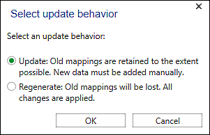
- The configuration is updated. The warning symbol disappears.
Preparing the Master: - Select the CANopen master with the mouse.
- Change if required the “Node ID” (e.g., “126”) and the baud rate (e.g., 250000) in the “Settings” panel in the “CANopen” tab.
Note that node IDs within a CANopen network must always be unique. - Open the CANopen fieldbus configurator for the master: click the CANopen connector of the CANopen master and click [Configurator] in the context menu.
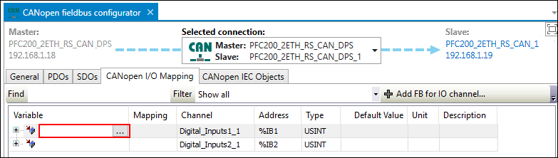
- Open the “CANopen I/O Mapping” of the CANopen fieldbus configurator.
- Assign variables to the channels created in the slave by clicking on the appropriate variable field and entering a variable.
Alternatively, use the Input Assistant by clicking the […] button.
The configuration is then complete. The variables can be used in e!RUNTIME programs of both devices.
For additional information see:
- Panel “Settings” > “CANopen” Tab
- Configuration of Communication Connections > CANopen Fieldbus Configurator
- Configuration of Communication Connections > CANopen Data Point Configurator