Creating a Simple PROFIBUS Network
To create a PROFIBUS network, you need at least one PROFIBUS master and one slave. The PROFIBUS slave function is provided with a PFC200 (order number 750-8206). The configuration of the PROFIBUS slave requires a connection to a generic PROFIBUS master.
- Place the generic PROFIBUS master and the PROFIBUS slave in the Network view (Communication view).
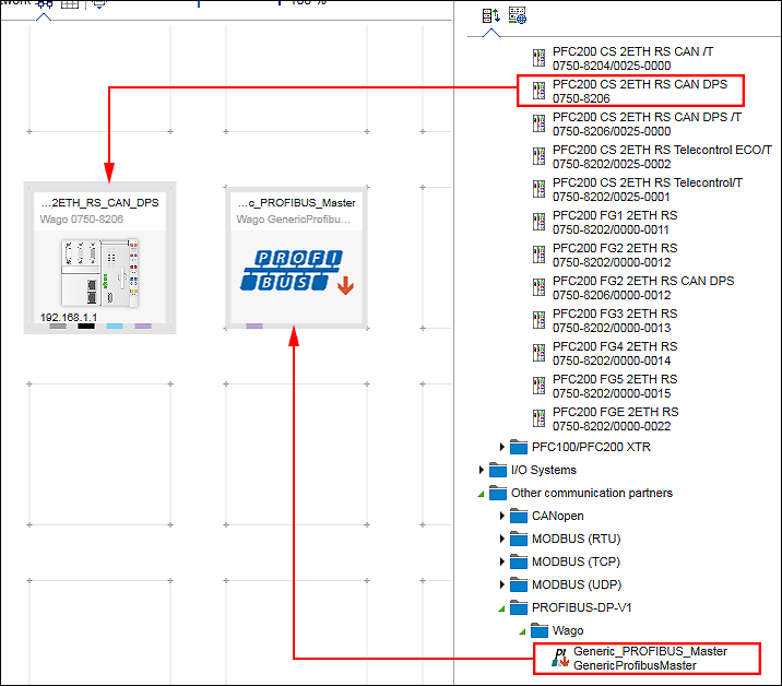
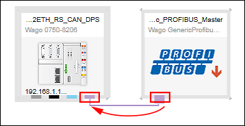
- Create a connection between both devices by connecting up the PROFIBUS connectors (purple) with each other.
- In a PROFIBUS network, each device is assigned a unique address. The PROFIBUS address is set in the “Settings” panel.
- If the “Settings” panel is not yet opened, open it by right-clicking the slave device and clicking the [Settings] button.
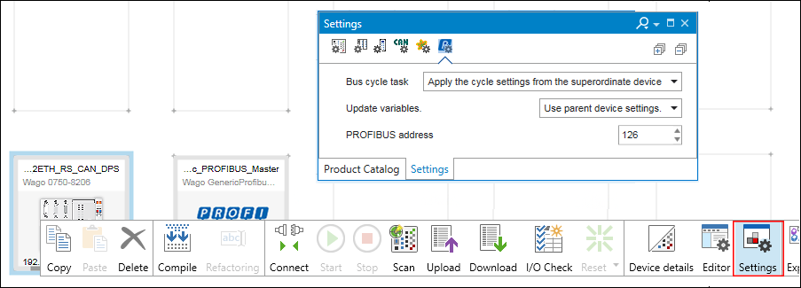
- Click the tab in the “Settings” panel in which the PROFIBUS address is set.
- Enter a unique address in the “PROFIBUS Address” entry field.
- The communication in the PROFIBUS network is performed using data points. These are set in the configurator of the PROFIBUS connection for the PROFIBUS slave.:
- Open the PROFIBUS data point configurator by double-clicking on the PROFIBUS device.
- The Device Detail view appears. The PROFIBUS data point configurator is displayed as the “PROFIBUS-Slave” tab. In the PROFIBUS data point configurator, defined variables are listed and new ones are created.
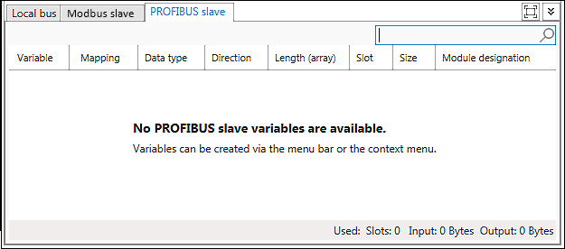
- Create a data point by selecting [New] in the context menu of the configurator.
Alternatively, click [Create variable] in the menu ribbon of the “PROFIBUS-SLAVE” tab. 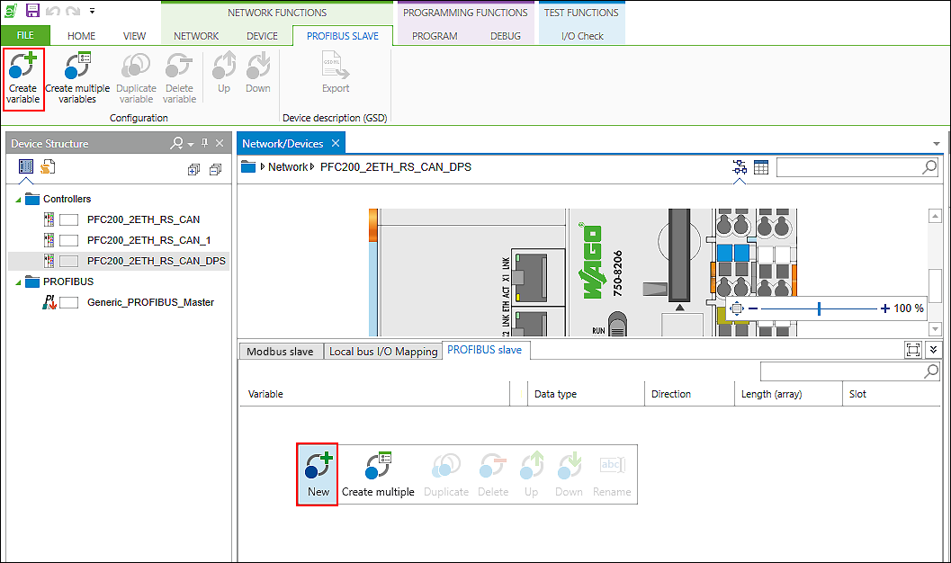
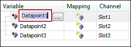
- The variable is created. The “Name”, “Data type,” “Direction,” Slot,” “Size” and “Module Designation” are provided with default values. These values are assigned for each new variable created.
Create additional variables and adjust the values as required. 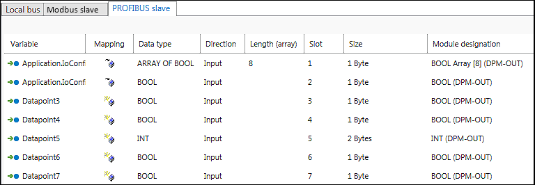
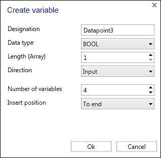
- Tip: To create multiple variables at once or to duplicate existing data points, use the corresponding [Create Multiple Variables] or [Duplicate Variable] buttons in the menu ribbon. In both cases these open a dialog in which multiple values can be set for the newly created variables.
 Note
NoteVariablen an beliebiger Stelle platzieren!
Haben Sie keine Variable in der Liste ausgewählt, dann wird die neue Variable an der letzten Position platziert. Haben Sie eine oder mehrere Variablen ausgewählt, wird die neue Variable hinter der letzten selektierten Variablen platziert. Auf diese Weise können Sie die neue Variable an beliebiger Stelle einfügen. Nachträgliches Ändern der Position ist auch über das Kontextmenü möglich ([Nach oben]/[Nach unten]).
- You can delete the variable if required in the same way ([Delete] in the context menu of the corresponding variable or [Delete Variable] in the menu ribbon).
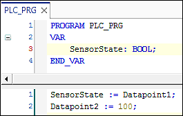
- After a variable name is assigned, an application variable with the same name (global variable list) is created automatically in the background. You can use this variable in your IEC program.
- You have two options for mapping created application variables to data points:
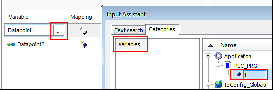
- Double-click the corresponding variable name and enter the name of the existing application variable manually.
- Or click the […] button to open the Input Assistant and to select the application variable there.
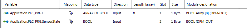
- The mapping is performed.
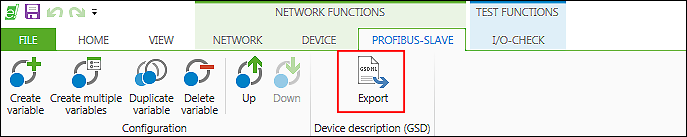
- After the variables are created and optional mapping, you can save the configuration in the form of a device description file.
- Click the [Export] button in the “PROFIBUS-SLAVE” tab of the menu ribbon.
- The “Save As” dialog for entering a file name is opened.
- Enter a name and confirm with the [OK] button.
- Two files are saved. The two files contain identical configurations. Only the description language of the parameters is different. The file with the suffix “*.gsg” contains German text. The file with the suffix “*.gsd” contains English text.
- The exported device description can be imported by other engineering tools.
For additional information see:
- Panel “Settings” > “PROFIBUS” Tab
- Configuration of Communication Connections > PROFIBUS Data Point Configurator