Creating a Simple PROFINET Network
To set up a PROFINET network, you need at least one PROFINET IO controller (master) and one PROFINET IO device (slave). The PROFINET IO device functionality is, for example, provided by a PFC200 (item number 750-8215). To configure the PROFNET IO device, a connection to a generic PROFINET IO controller is required.
- Place the generic PROFINET IO controller and PROFINET IO device in the Network view (Communication view).
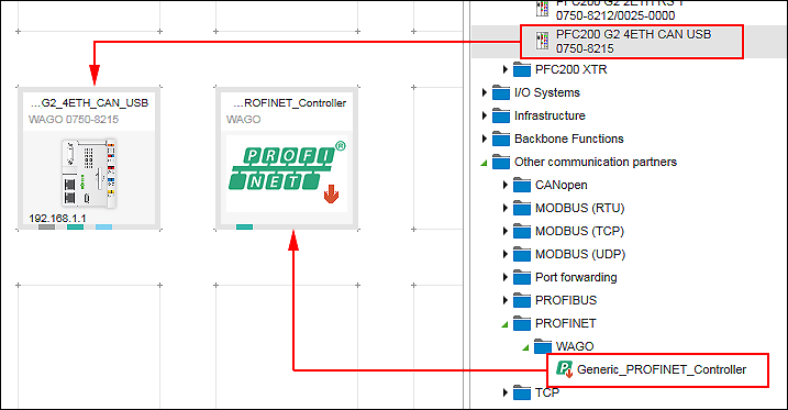
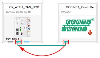
- Create a connection between both devices by connecting the PROFINET connectors (green) to each other.
- In a PROFINET network, each device must have a unique station name. The name is defined by the device or device description file. The name can be changed in the “Settings” panel as needed:
- If the “Settings” panel is not yet opened, open it by right-clicking the I/O device and clicking the [Settings] button.
- Click the “PROFINET I-Device” tab in the “Settings” panel“.
- Using the same station name in the network and e!COCKPIT is recommended. The option “Synchronization with e!COCKPIT device names” ensures that the same name is used. Only switch of synchronization in exceptions if required. In such case, you could change the station name.
- Data points are used for communication in the PROFINET network. The data points are set in the PROFINET data point configurator for the PROFINET IO device.
Open the PROFINET data point configurator by double-clicking on the PROFINET IO device. - The Device Detail view appears. The PROFINET data point configurator is displayed as the “PROFINET I-Device” tab.
PROFINET modules with defined variables are listed and created again in this tab. - Create a PROFINET module. A module contains one input and one output variable. To create the module, click [Add] in the context menu of the configurator.
Alternatively, click [Add] in the menu ribbon, “PROFINET I-Device” tab. 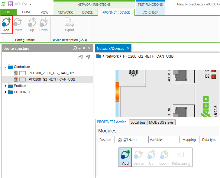
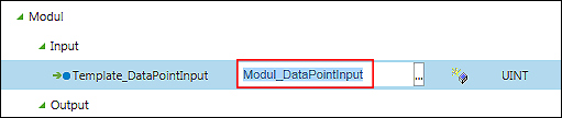
- Module and variables are created. The “Name”, “Variable” and “Data type” fields initially contain default values assigned for each newly created variable.
- Create additional variables and adjust the values as required:
Change the name, data types or description by double-clicking the respective data type field and changing the respective value. You can make other changes, such as renaming or deleting variables, as well as moving modules up/down from the context menu or in the menu ribbon, “PROFINET I-Device” tab. - If you use the “Refactoring” function to rename variables (context menu), the application variables are also renamed automatically in the background (global variable list). You can use these variables in your IEC program.
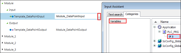
- You have two options for mapping created application variables to data points:
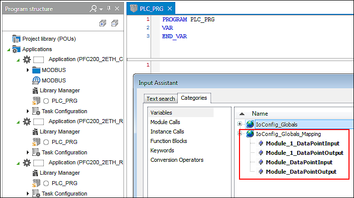
- Double-click the corresponding variable name and enter the name of the existing application variable manually.
- Or click the […] button to open the Input Assistant and to select the application variable there.
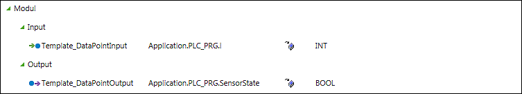
- The mapping is completed.
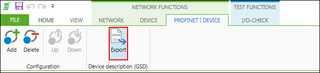
- After the variables are created and optional mapped, you can save the configuration in the form of a device description file.
- Click the [Export] button in the “PROFINET I-Device” tab of the menu ribbon.
- Use [Browse] to select the target location for exporting the device description file.
- Click [Export] to save the file.
A GSDML file (XML format) is saved for each connected PROFINET IO controller. Other engineering tools can be used to import.
The file name contains the name of the IO device and the name of the connected IO controller:
GSDML-[Version]-wago-[Name IO Device]_[Name IO Controller]-[Date].xml
Example:
GSDML-V2.32-wago-8215_PFC200_G2_4ETH_CAN_Controller-20180503.xml
The “GSDML_Wago_750_8215.bmp” image file is also saved, which is used to represent the device in other engineering tools.
So that the contents of the device description can be assigned in other engineering tools, the information entered for generating the content of the GSDML file is integrated as follows:
Representation in | Mapping in GSDML File | Description |
|---|---|---|
Position | ModuleItem@ AllowedInSlots | The position in the PROFINET I-Device Data Point Configurator corresponds to the slot of the defined module. It can only be plugged into this slot in “IO Controller Engineering”. |
Module name | ModuleInfo/Name | Serves as name in the information description of the module. The name is listed in the “IO Controller Engineering” product catalog. |
Module description | ModuleInfo/Info | Description of the module in the “IC Controller Engineering” device catalog. |
Data type Input/Output | SubmoduleItem/IOData/Input | The data type selected in e!COCKPIT is mapped to the data types suitable in the GSDML specification. The mapping of the GSDML data types in the engineering tool of the IO controller may not be directly apparent. The information about the data type is added to the module description (ModuleInfo/Info) in the product catalog. Example: “IN BYTE[42]; OUT DWORD” |
Data type name | DataItem@TextId | The name of the data type in e!COCKPIT is added to the associated data item as text in the GSDML file. Mapping in the engineering tool of the IO controller depends on the manufacture and may not be imported. |
For additional information see:
- Panel “Settings” > “PROFINET I-Device” Tab
- Configuration of Communication Connections > PROFINET Data Point Configurator