Creating a Simple Modbus Network
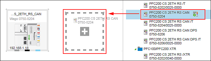
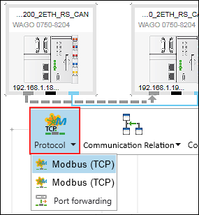
- Select two devices from the Product Catalog and drag them with the mouse into the Network view (Communication view).
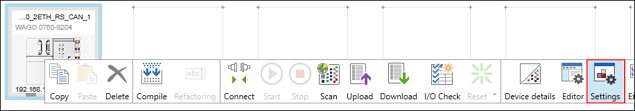
- To change the settings or parameters of the devices added, click the respective device, open the “Settings” panel in the context menu and make your changes there.
- Now connect the devices. Click the gray connector (ETHERNET/Modbus) for one of the devices in the Network view (Communication view) and hold down the mouse button.
- To connect the devices to each other, drag the connection line to the same type connector of the second device. Release the mouse button as soon as a green plus sign appears.
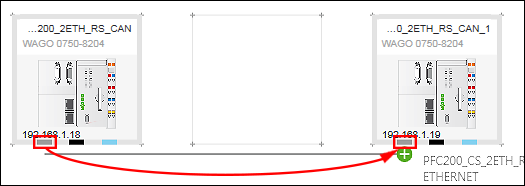
- The devices are connected. The role of the device defines the connection direction. The connection direction is indicated by an arrow and goes from master to slave.
You can change the master and slave device roles later as needed: - Click the Modbus connector of one or both devices.
- Click [Communication Relation] in the context menu.
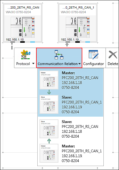
- The current communication relationship is highlighted in blue and displayed first.
- Select the second entry as needed.
In this example, you retain the communication relationship. - You can also specify the connection protocol.
- Click the [Protocol] button in the context menu of the Modbus connector.
- Select the required connection.
In this example, select “MODBUS (TCP)”. - The choices depend on the devices used.
If your device can be used as a router for off-network devices, “Port forwarding” can also be selected (see Connecting Off-Network Devices (Port Forwarding)).
You have defined the role of the device and the protocol used for the connection. Below you open the Modbus data point configurator.
Use the data point configurator to define what slave variables should be available on the master. - To open the Modbus data point configurator for the connection, double-click on the device tile of the slave device in the Network view (Communication view).
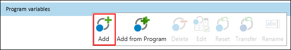
- The Device Detail view appears. The Modbus data point configurator opens in the “Modbus slave” tab.
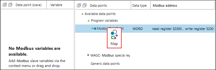
The figure below shoes the Modbus data point configurator after opening. No communication variables between the master and slave have been defined yet. 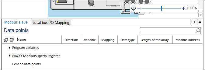
- To create variables, right-click “Program variables”.
- Click the [Add] button in the context menu.
- The variable has been created as a global variable in the slave application and can be used there.
The table row displays the default values for Modbus access to the new variable. 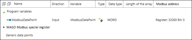
- To change the default values, double-click the individual fields “Direction”, “Variable”, “Data type”, etc.
- To make settings regarding the Modbus address, right-click on the row of the newly created variable.
- In the context menu, click [Edit] and adjust the settings as needed.
 Note
NoteAdditional Information to “Generic data points”
You can also create “Generic data points” in the same way as “Program variables”. The [Edit] button is used for generic data points and Modbus special registers to open a dialog with further setting options, e.g., for setting function codes.
Generic data points and Modbus special registers are not available via the slave application: Modbus special registers are only available in the Modbus stack of the slave and accessible via Modbus only. There are application cases in which it makes sense to use generic data points. For example, you can group multiple data points into one register to access different masters without having to create manual channels for every access in the master.
- Go back to the Network view (Communication view).
- Below you open the Modbus fieldbus configurator. Mainly connection settings are made here, Modbus master variables displayed and created.
- Click the Modbus connector of one or both connected devices.
- Open the Modbus fieldbus configurator by clicking the button [Configurator].
- The Modbus fieldbus configurator for the master opens.
The configurator is divided into two columns: The variables on the master are displayed on the left. The variables available on the slave and used in the slave application are displayed on the right. The tree displays them in a hierarchical view according to the program structure. - Select the slave variable created in the right column.
- Note
Simple and complex data types possible!
I/O modules make their data available as individual variables. Some I/O modules also make data available as an array/structure. Depending on where and how deep you are in the tree structure of the fieldbus configurator and where you click [Map], you can either access the individual variables, arrays or the entire I/O module for these I/O modules. This option is available if a fieldbus coupler is used as the head station because it forwards data unchanged from the I/O modules via the bus and allows full access to the data structures of the I/O modules.
Controllers, on the other hand, have the task of first processing data from the I/O modules and only passing on the result via the bus. Application variables ("Program variables") are linked within the application with data from the I/O modules and only then are they communicated via the bus. The configuration is therefore not created automatically.
- Note
Tip: Providing i/o modules with all data points
In addition to providing individual data points, some I/O modules*) can also be provided as a whole with all data points for the master. The data points of the I/O modules are accessed uniformly, regardless of whether the I/O modules are connected directly to the controller or are addressed remotely via Modbus. When the data points are provided, program blocks and instances of prepared function blocks are automatically generated, via which the data exchange is implemented. You can use these program blocks directly in your program without further adjustments.
*) The provision of complete data structures is possible for those I/O modules whose associated function blocks offer an iPort for connections:
0750-0636, 0750-0642, 0750-0643, 0753-1630, 0753-1631, 0753-0646, 0753-0647, 0753-0649, 075x-0482, 075x-0484, 075x-0493, 075x-0494, 075x-0495, 75x-0632, 075x-0635, 075x-0640, 075x-0644, 075x-0645, 075x-0650, 075x-0651, 075x-0652, 075x-0653, 075x-0655, 075x-0657, 075x-0658, 075x-0670, 075x-0671, 075x-0672, 075x-0673, 075x-0511, 075x-0633 - Click [Map] in the context menu of the variable.
- According to the path (namespace) in the slave application, the created slave variable is generated in the master application. It is then available on the master directly.
The slave data point (1), the variable created on the master (2), the selection field for the data type (3), the cycle time for updating the variables via Modbus (4) and Modbus access to the variables (5) are displayed.
ReadOnly (RO): Master reads the slave output.
WriteOnly (WO): Master writes to the slave input.
ReadWrite (RW): Master reads the slave output or writes to the slave input 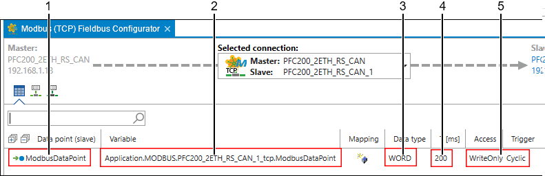
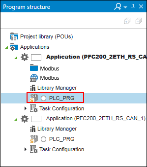
- Open the “Program Structure” panel and the main program of the master.
In the master application, access to the “ModbusDataPoint” variable as shown in the following figure.
Tip: Press the [F2] key to open the Input Assistant for easy variable selection.
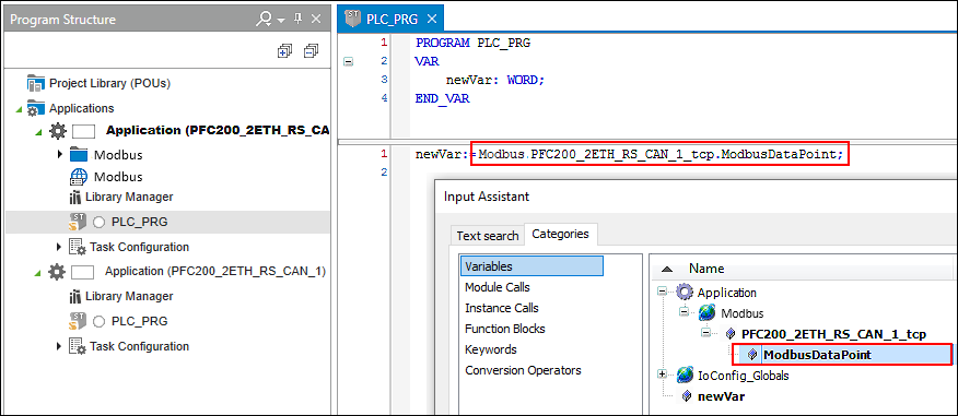
In this way, a variable has been declared in the slave application, made accessible via Modbus and read in the master application.
For additional information see:
- Panel “Settings” > “Modbus Slave” Tab
- Configuration of Communication Connections > Modbus Fieldbus Configurator
- Configuration of Communication Connections > Modbus Data Point Configurator