I/O Check
Based on the device view, wiring tests can be carried out for conventional, analog and digital inputs/outputs of a device, for example by setting output signals for test purposes (see also 8 Performing Device Diagnostics).
 Note
Note
Not all devices support testing of inputs and outputs
Please note that not all devices support testing of inputs and outputs. Only the device view with the status indicators is available for these devices.
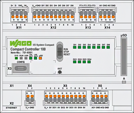
The device hardware used is visually displayed in the upper area of the “I/O Check” view. The LED indicators on the left show the status of the head station and the LED indicators on the right show the status of the channels.
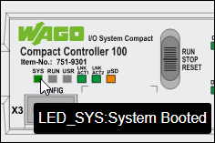
Head Station Status Indicators
The head station status indicators are always enabled. The LED indicators in the graphic are not clickable, but they do show the current status message of the head station on mouseover.
Note
Flash codes are not displayed in real frequency
Note that the flash codes are not displayed in real frequency.
Detailed descriptions of the diagnostic messages and flash codes can be found in the manual for the respective product.
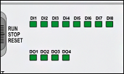
Channel Status Indicators
The status indicators for the connected channels do not show the current status (read-only) of the digital inputs and outputs in permanent fashion, but only in monitor mode. Monitor mode is enabled if there is an online connection to the device.
Note
LED status refers to on/off status values related to digital I/O channels
For diagnostic channels, the physical LED indicators may consist of several status values. The LED status displayed here only refers to on/off status values directly related to digital I/O channels.
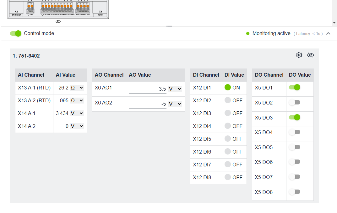
Clicking on the eye icon below the respective device displays tables with status values for the channels of the inputs and outputs used. The indicator can be switched between control and monitor mode.
Control | Description |
|---|---|
| Zoom in |
| Zoom out |
| Original size |
| Adjusts the size of the displayed areas |
| Tables with status values hidden |
| Tables with status values displayed |
| Switches directly to the settings of the I/O channels |
| Control mode enabled |
| Monitor mode enabled |


The latency is also displayed, i.e., the update cycle (in s) of the displayed device values depending on the connection, device load or other factors:
Display | Description |
|---|---|
| Low latency, high synchronization rate |
| Higher latency, delayed synchronization rate |
| High latency, unstable connection |
 Monitoring active
 Monitoring active
 Connection unstable
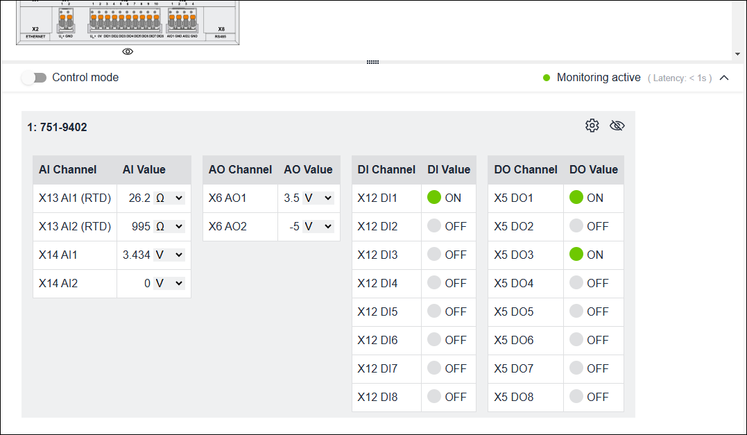
Display/setting of status values
Status values can be shown as follows using selection fields:
- as raw values or
- as scaled values with units.
Scaled representations can only be set on the user interface; raw values are still used for communication.
Sliders can be used to set digital values:
- Switch setting
 corresponds to 1 or true
 - Switch setting
 corresponds to 0 or false
Note
“I/O Check” view may not show original channel configuration
For devices that support variable channel configuration (e.g., WAGO Compact Controller 100, Item no. 751-9402/xxx-xxx), the assignment of the channels can be changed in the “Settings” > “I/O-Channels” view. The “I/O Check” view then shows the modified channels instead of the original ones.
Tip:
You can also access an overview of the LED indicators/status messages via the “Settings” > “LEDs” view.
In addition, each page has a “Device Status/Actions” section via 8 Settings.