Slave Settings in the Data Point Configurator
The data point configurator is used to configure the fieldbus interface of a slave device. The slave data points accessible via Modbus are created and configured here. The data points that the slave makes available to all masters are specified.
If the slave is a fieldbus coupler or a third-party device, a data point overview resulting from the node structure is displayed in the data point configurator. From the available data points, you can select the ones that should be accessible to Modbus master devices.
If a controller is used as a Modbus slave, data preprocessing can also be performed in the controller if necessary. In this process, application variables are mapped to data points. However, this is not usually necessary. The data points are also available to Modbus master devices.
You can open data point configurators by double-clicking on the device tile (Network view) below the Device Detail view. They are also accessible from the fieldbus configurator.
Data point configurators are displayed in individual tabs according to the specific protocol. If devices are selected in the Network view that communicate via multiple protocols, tabs are displayed for all applicable protocols.
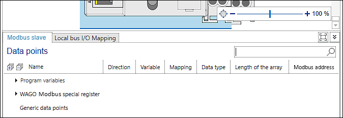
The Modbus data point configurator is shown on the “Modbus Slave” tab:
Parameter | Description | ||
|---|---|---|---|
Name
| Name of the Modbus data points Data points are displayed in group as follows:
| ||
Note: You can find a more detailed expansion of the Modbus data points in Overview of the Modbus Data Points. | |||
Direction | Indicates whether the data is input data or output data | ||
Input
| The value of the variable is set exclusively via the bus and is readable in the program. Write access in the program does not make sense because the value is constantly overwritten from the outside. | ||
Output | The value of the variable is set in the program and is only readable from the outside. | ||
Input/Output | The value of the variable can be read/set by the fieldbus as well as by the program. Note: If you only use the variable for the visualization as Input/Output, then make sure to select the option “Always update” in the “Settings” panel, “Modbus master” tab under “Updating variables”. Otherwise the variables are not updated in the visualization. | ||
Variable | Name of variable The name is always identical to the name of the application variable. | ||
Mapping | Indicates which variable is new and which variable already exists: | ||
| The variable is not yet available, will be newly created and can then be used in the entire project. | ||
| An existing variable is used for mapping. | ||
Data Type | Displays the data type of the Modbus data point, and thus of the application variable. The following data types are supported: | ||
• BOOL | • ARRAY OF BYTE | ||
Length of the Array | Displays the number of elements for arrays | ||
Modbus Address | Displays the Modbus address of the variable – bit-based (coil) or register-based | ||


Individual values of a row, e.g., data point names, can be changed by double-clicking on the respective entry. Note that no periods (“.”) can occur in the name.
If the information icon (“i” in a blue circle) is displayed, this indicates that there are addressing overlaps. In other words, multiple data points are using the same memory register. Double-click to modify the memory register.
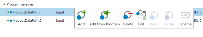
To create or edit a new data point, the following functions are available in the context menu (right-click on a row):
Symbol | Button | Description |
|---|---|---|
| [Add] | Adds a Modbus data point Note: Use [Add] for access to I/O modules of controllers (CODESYS V2), for example; see scenario Connecting Controller (Master) to Controller (CODESYS V2) (Slave). For program variables, use [Add from Program] (see below). |
| [Add from Program] | Adds Modbus data points that represent variables of a controller program Note: Use of this is described by an example in scenario Connecting Controller (Master) to Controller (Slave).
One or more existing variables can be selected from the PLC program that are to be published via Modbus. [OK] adds the variables in the data point configurator. [Cancel] closes the dialog. Note: Simple data types are transferred directly via Modbus, while complex data types (including structures) are mapped to word arrays. These are then transferred via Modbus instead. If the data type used is known globally in the project, the master can directly access the individual elements of the complex variables, although Modbus does not use such a data type itself (see also Access to Simple and Complex Data Types). |
| [Delete] | Deletes the Modbus data point |
| [Edit] | Opens a dialog with further options (see description in the table below) |
| [Reset] | This button is available if a name has been changed. The name of the mapping variable is reset to the default name (data point name). |
| [Transfer] | This button is available if a value has been changed (e.g., “Input” to “Output”) and then multiple rows have been selected. |
| [Rename] | This button is available if the data point configurator has been opened for the slave device and there is a connection to another device. Clicking [Rename] opens a dialog to rename the variable. |


The [Edit] button opens a dialog with further setting options. The settings options differ according to the group (“Program variables,” “Modbus Special Registers” or “Generic Data Points”).
Parameter | Description |
|---|---|
Explicit Access | Excludes the variables from any optimizations of the Modbus master |
Function Code (Read) | Function codes for reading the variables |
Address (Read) | Address for reading the data point in the Modbus process image |
Function Code (Write) | Function codes for writing the variables |
Address (Write) | Address for writing the data point in the Modbus process image |
Modbus Address | If available: setting for bit-based (coil) or register-based access of the master Specific function codes are used according to the setting. |