Network/Bus Connections
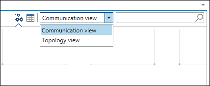
Connections are either physical (Topology view) or logical (Communication view). Depending on the application, both views can be used to view a project. There is a drop-down menu in the Network view to switch between views.
Communication View
In the Communication view, devices are connected to each other logically using common protocols (e.g., CANopen). The mouse is used to drag connecting lines between two connectors of the same type.
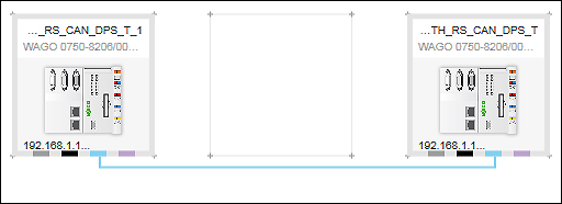
The direction in which the devices are connected defines the role of the device. The connection is made from master to slave.
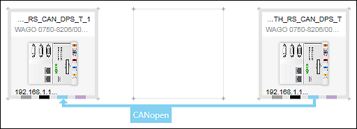
If you put the mouse on a connecting line, the direction of communication is indicated by an arrow. The protocol is also displayed on the connecting line.
If a project controller is connected with an off-network device that is only connected to the controller by port forwarding, “Port Forwarding” is displayed for this connection instead of the protocol name.
To control data exchange, each logical connection can be further configured via the buttons in the context menu of the connector (see Connectors). You can also change the direction of communication later from the context menu of the connector ([Communication Relation] button).
Topology View
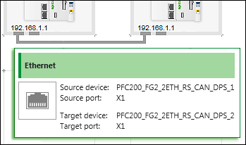
Physical connections in the Topology view correspond to cables between devices that are compatible with their hardware, i.e., their terminations. In the Topology view, the mouse is also used to drag connecting lines between two connectors of the same type. The direction is not important.
If the mouse touches the connecting line, start and target device, as well as the respective connected ports of the device are displayed.
Connections between devices can be created in both the Topology view and Communication view.
The color of a connecting line corresponds to the respective connector color of the protocol (see Connectors).
If the connecting line is surrounded by a red dashed line, there is an error in the network (see General Status Display for Connections).
For the Modbus, CANopen and PROFIBUS protocols, there is a port/connector in both the Topology view and Communication view for each fieldbus connection. For ETHERNET, multiple ports/connectors can be displayed in the Topology view if devices have more than one RJ-45 network connection.