Connecting a Controller (Master) to a WAGO Device (Slave)
In what follows, you connect a 750-8216 Controller (EtherNet/IP scanner as master) with a 750-363 Fieldbus Coupler (EtherNet/IP adapter as slave).
The 750-8216 Controller is used here as an example. Another PFC200 second-generation controller, an edge controller or a touch panel can also be used here (see supported devices under WAGO Devices as EtherNet/IP Masters (License Required)).
Instead of the 750-363 Fieldbus Coupler (and its variants), EtherNet/IP devices of the WAGO I/O System Field can also be used, for example (see supported devices in WAGO Devices as EtherNet/IP Slaves).
The 750-363 Fieldbus Coupler is already integrated into the product catalog via an EDS file.
 Note
Note
Connect EtherNet/IP devices to port X1 of the controller!
Always connect EtherNet/IP devices to port X1 of the controller. Only this port is used for EtherNet/IP communication.
Place Devices on the Communication View
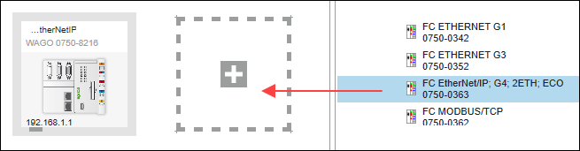
- Select the controller and fieldbus coupler from the product catalog and use the mouse to drag them into the Network view (communication layer).
Configure I/O Modules Used in the Device Detail View
- Open the Device Detail view (in either graphical and tabular view) by double-clicking the fieldbus coupler.
- Note: If you do not see a graphical node view for the WAGO fieldbus coupler, you are not using the current version of the device, but an outdated version (marked as “deprecated” in the product catalog and in the tool tip for the device). Although the device is fully functional, input/output data must be created manually. Newer WAGO fieldbus couplers automatically generate input/output data from the node configuration. If you want to switch to a new version, delete the old device from your project and add a new one. Please note that any existing mapping in the fieldbus configurator must also be recreated in this case.
- Arrange the I/O modules used analogously to your hardware by dragging them from the product catalog and positioning them after the device.
- Parameterize the I/O modules as needed by selecting them and making changes on the “Settings” panel for each.
- Note: If you change the operating modes / process image lengths / mailbox sizes for an I/O module, click once on the “Input/Output data" tab after the configuration to update the display for the byte sizes of input/output data points.
- Go back to the Network view.
- Proceed in the same way with the second device.
Connect Devices
- Click the gray connector (Ethernet/IP) for one of the devices in the Network view (communication layer) and hold down the mouse button.
- To connect the devices to each other, drag the connection line to the same type connector on the second device. Release the mouse button as soon as a green plus sign appears.
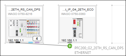
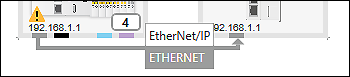
- The devices are connected. The arrow of the connection line indicates the automatically assigned roles of the device: The connection line starts at the master and ends at the slave.
- A yellow warning symbol in the device tile of the master indicates that a license is required to use the EtherNet/IP functionality.
- You can run the device without a license for 30 days in evaluation mode. Otherwise, follow the steps below.
Use License for EtherNet/IP Master
- If you have already purchased a license, first enter it in e!COCKPIT: Backstage View > “Licensing” page, [License Management] > [Enter Licenses].
- Once you have entered the license, open the “Available Licenses” and “Project Licensing” panels (via the ribbon > “VIEW” tab >[ Available Licenses] button and [Project Licensing]).
- Use the “Auto-assign everything” option on the “Project Licensing” panel (recommended).
Alternatively, drag the license from the “Available Licenses” panel to the appropriate device on the “Project Licensing” panel, or drag the license directly onto the device in the Network view. - Then load the license onto the device by synchronizing it (the [Synchronize] button on the DEVICE tab of the ribbon or on the “Project Licensing” panel).
Note
Information about licensing in the e!COCKPIT product manual:
The e!COCKPIT product manual describes in detail how licensing is handled. It describes how to acquire licenses, activate them, assign them to devices and link them in the device (see “Purchasing a License,” “Activating the License” and “Activating Runtime Licenses” in the e!COCKPIT product manual).
Note
“WAGOupload” can be used for series commissioning
The “WAGOupload” software is available as an alternative for commissioning a larger number of controllers. This software can also be used to load licenses and projects onto controllers.
Make the Device Settings on the “Settings” Panel
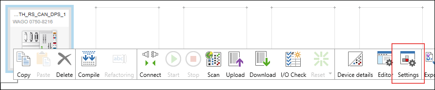
You can change the settings or parameters of the devices that have been added on the “Settings” panel. The panel is open by default. If it is not, open it using the context menu of the device and the [Settings] button.
The tabs, entry screens and selection fields on the “Settings” panel depend on the specific device. Which settings options are displayed depends on the content of the specific device description file.
Controller (Master):
- Select the controller (master) in the network view.
- First set the EtherNet/IP interface of the controller:
On the “Device” tab of the “Settings” panel, enter the IP address of the controller.
Note: This change requires the master to be offline. 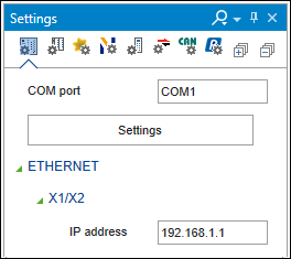
- To load further data of the controller into e!COCKPIT, click the [Settings] button on the same tab.
- The integrated “WAGO Ethernet Settings” tool opens.
- Wait until the controller configuration appears.
- Close “WAGO Ethernet Settings” again.
- Confirm the transfer of the configuration data to e!COCKPIT with [Apply].
- The display is updated on the “Device” tab of the “Settings” control panel:
For example, the MAC address of the controller now appears here.
Note: EtherNet/IP uses only network interface X1 for communication.
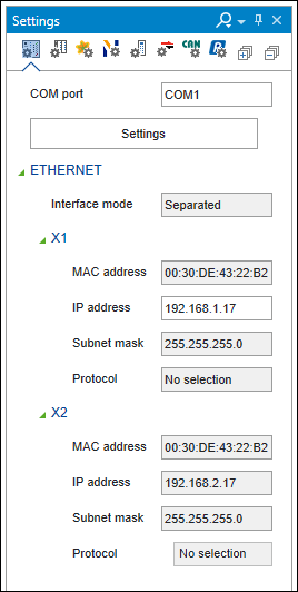
Note: The “EtherNet/IP” tab of the control panel also contains the IP address and MAC ID, but is for information only. Only the “Device” tab is used for making settings.
Fieldbus Coupler (Slave):
- Select the fieldbus coupler (slave) in the Network view.
- On the EtherNet/IP” tab of the “Settings” panel, you can see that the slave device already contains device information. This is type plate data from the EDS file. This data does not have to be modified.
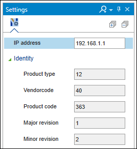
- Enter the IP address of the slave.
Configure Slave
You configure the slave in the data point configurator.
- Open the data point configurator by double-clicking on the device tile of the slave.
- First start on the open “Connection” tab.
- This tab already contains entries. These concern Connections described in the EDS file and created with its predefined parameters.
Edit Connection:
- Select one of the connections and click the [Edit Connection] button.
- The “Edit Connection” dialog appears.
- Here you can change the name of the connection, for example.
- For example, for WAGO devices, you can specify which data of the connected I/O modules should be used for the connection under “Path”.
For instance, you can select only the analog input modules. - Confirm your changes with [OK].
Tip: The connection between input/output data points and handling via assembly instances is illustrated in the Example Configuration for Data Exchange with a WAGO EtherNet/IP Fieldbus Coupler 750-363.
Create Additional Connections (Optional):
- Create a new connection by clicking the [Add Connection] button.
- In the “Add Connection” dialog, specify the parameters of the connection (see “Connection” Tab).
- To create the connection, click [OK].
- The connection appears in the list.
Adjust Input/Output Data Points for Connections:
Note: For WAGO fieldbus couplers, input/output data are created and modified automatically based on the node structure. The input/output data points can only be created and modified as described below for generic connections that you have created yourself.
- Select the connection for which you want to view or edit input/output data points.
- The input/output data points for the selected connection are displayed on the “Input/Output Data” tab (if they are already predefined via the EDS), and the display is context-sensitive.
If this is an “Exclusive Owner” connection, you see data points for inputs (T→O) and data points for outputs (O→T) here, for example. - To modify entries directly in the table, double-click the respective fields.
Create New Input/Output Data Points (Optional, or for Connections You Have Created Yourself):
For modular devices and generic connections, you must create the input/output data points manually.
Note: Note which options the device offers, for example, which assemblies are supported. This information can be found in the corresponding product manual. Also note the node configuration used (I/O modules, number, type etc.).
- To create an input data point, right-click “Input (T → O)” and select [Add].
- To create an output data point, right-click “Output (O → T)” and select [Add].
- Tips: Alternatively, you can create multiple data points by selecting [Add multiple].
If you want to create data points at a specific location in the data point list, then select Add/Add multiple in the context menu of one of the existing data points. - If necessary, adjust the name, data type and bit size by double-clicking the relevant value of the input/output data point.
- If necessary, adjust the parameters for the input and output size of the connection.
- To apply the changes, click [Enter].
You have now defined the data points for the selected connection(s). The connections and data points are offered for selection in the fieldbus configurator for the controller.
Settings on the “Target Configuration” Tab:
Settings on the “Target Configuration” tab are not required for the 750-363 Fieldbus Coupler because they are not defined in the EDS file.
Other slave devices may have parameters here. You can then edit these further (see “Target Configuration” Tab).
Set User Parameters:
- Switch to the “User Parameters” tab.
- Parameters that are defined in the EDS file are displayed here. Only the “Failure Reaction” value is predefined for the 750-363 Fieldbus Coupler.
- In the “Failure Reaction” selection field, specify how the fieldbus coupler should react in the event of an error.
- Advanced setting: If necessary, you can create additional parameters. To do so, click Add in the context menu. However, this requires you to know the exact path and valid data types/values.
- To apply the parameter(s) for the device, click the corresponding checkbox in the “Write” column.
Note: Note that writing only is performed if the “User Parameters” option is enabled in the fieldbus configurator on the “Communication Settings” Tab (enabled by default).
- The configuration of the slave is completed.
Configure Connection between Master and Slaves
You can configure the connection between the master and slaves in the fieldbus configurator. Here the connections configured in the slave are displayed with their data points and made available for the controller.
- Click the EtherNet/IP connector of one of the two connected devices.
- Open the EtherNet/IP fieldbus configurator by clicking the [Configurator] button.
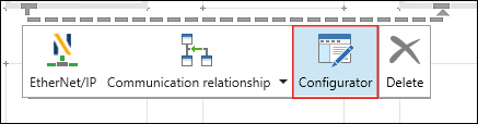
- The fieldbus configurator opens. The connection is shown in the header section of the configurator. If multiple slaves are connected to one master, you can modify the selection under “Selected Connection.”
- The fieldbus configurator is divided into two columns:
On the left side, the “Communication Connections” opens first; this shows the connections with the data points that are transferred via the bus from the slave to the master.
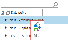
The right side shows the connections available on the slave. In addition, the input/output data is displayed with the individual data points in a tree structure. - For connections to be established by the master when connecting, use the mouse to drag the desired connections from the right section to the left section (“Communication Connections” tab). Alternatively, select Map in the context menu of the connection.
- Note: Connections are always provided as a whole with all data points for the master.
Configure Connection:
- To further configure the connection, click the [...] button to the left of the connection.
- The “Edit Connection” dialog opens.
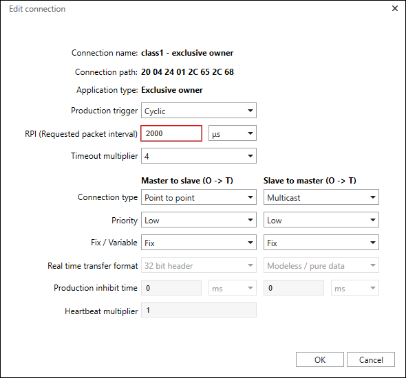
- Make the settings according to Fieldbus Configurator – “Edit Connection” Dialog. Usually, no changes are required for the WAGO device.
- Click [OK].
Perform Mapping between Data Points and Program Variables:
- To map data points of the connection to program variables or to create new program variables by mapping, double-click within the relevant input field of the “Variable” column.
- Assign a name. For example, enter the variable “in” for the first input data point and the variable “out” for the first output data point.
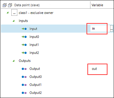
- The mapping creates new global variables in the master application. This establishes the connection to the slave.
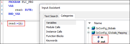
- Tip: The [...] button to the right of the variable field opens the input assistant. There, as an alternative, you can select program variables that already exist for the mapping.
- Note: Only program variables of data type BYTE can be mapped to input/output data points of data type BOOL.
Access Data Points
- Open the program structure and the main program of the master.
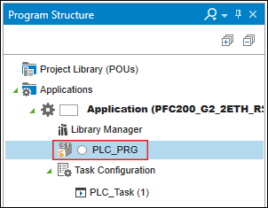
- Use the variables in your program.
For example, create a variable “read” in your program that reads in the word from “in”:read:=in;and/or write a value to the variable “out”:out:=16#ABAB; - Tip: Press the [F2] key to open the input assistant for easy variable selection.
- In this way, slave data points of an EtherNet/IP connection can be used for the master or in the program of the master.
Make Communication Settings
- Switch back to the fieldbus configurator.
- Open the “Communication Settings” tab.
- By default, the “Compatibility Check” option is selected here, which ensures that the slave performs a compatibility check for the type plate parameters. For the fieldbus coupler, this setting can be retained.
- You can find more information on how the compatibility check works in “Communication Settings” Tab.
Testing the Configuration
- Switch to the Network view and select the master.
- Click the [Connect] button in the ribbon.
- Confirm the message window for the parameter changes with [OK].
- Log in to the device.
(For new WAGO devices where the access data has not been modified, use the username “admin” and password “wago”). - The device is connected.
- Open the “PROGRAM” tab in the ribbon and click the [Start] button.
- The program is running. You can now test the connection and the data exchange in the fieldbus configurator or in the Web-Based Management of the controller:
- Testing in the Fieldbus Configurator:
Open the “Communication Status” tab in the fieldbus configurator. - Here you see the message “Adapter is running.”
Note: If the status does not update automatically, click the [Acknowledge slave diagnosis] button. - If the value shown is “NumDiagSlaves” = 0, all the slaves are configured correctly.
If not, check whether the entered data types and sizes of the input/output data points of the connection match the data sizes of connected I/O modules. - Testing the Configuration in Web-Based Management:
Note: Note that only WAGO devices have Web-Based Management.
Open the Web-Based-Management of the master by entering the IP address in a browser window.
Open the “I/O Data” page in the Web-Based Management. - Here you can see all input and output channels with the values that you have specified in the program or that were read in.
Note
Check WBM settings if EtherNet/IP communication fails
If no EtherNet/IP communication is possible, check whether the “Enable Binary Padding” function is deactivated in the WBM on the “EtherNet/IP” page of the fieldbus coupler (default setting). Only then is communication via EtherNet/IP possible. If, on the other hand, “Enable Binary Padding” is enabled, the assembly instances 101 to 109 are padded to an even number of bytes. This means that the byte size to be transmitted does not match that expected by the fieldbus coupler, so the communication is aborted.
Also check the header configuration set in the WBM: Only “Originator to Target” is activated for “RUN/IDLE Header”. Do not change these settings, otherwise the connection will be aborted, since the header information is already defined by the EDS of the device.